站点设定

仓库
语言设定
货币设定
资源
视频库
Cx Family Common Mode Chokes
0402CT Low Profile Chip Inductors
XAL7050 High-inductance Shielded Power Inductors
XGL4020 Ultra-low DCR Power Inductors

Support Center

We've put together some commonly asked questions to give you more information about the services and products we offer.

Don't see what you need?

常见问题

B and U Packaging Codes

Why are "B" and "U" packaging codes no longer required?
To simplify the Coilcraft part numbering (ordering code) system, the use of the "B" and "U" packaging codes (B = Less than full reel, U = Less than full reel) is no longer needed. When ordering, use the standard/default packaging code as shown on the data sheet. This update applies to all Coilcraft part numbers.

Note: When ordering samples, they will come in cut tape, unless otherwise requested in your comments. See Packaging Options below on this FAQ page.

Examples: 
BandUpackaging.jpg
Is the product changing?
No. The only change is to the packaging code.
Does this change affect form, fit or function?
No.
Has this product been designated as EOL?
No.
Has the part number changed?
No. The only change is to the packaging code.
Is the part obsolete?
No.

Buzzing Noise

During testing of our board, there is a buzzing sound from one of your inductors. Is this normal? Can it be eliminated?
That type of noise is usually due to a mechanical resonance in the component that is excited by the electrical conditions of the circuit, known as magnetostriction, and does not indicate a defect in the part. It is very dependent on the application conditions and is not always possible to eliminate by changes to the inductor alone.

Changing the switching frequency is often the best way to eliminate the noise. Applying a dampening material (electronic-grade encapsulant, potting compound, etc.) may decrease the sound level produced, or the increased mass of a larger component may dampen or shift the resonance to a different frequency.

Cleaning / Washing

What cleaning solutions can be used on Coilcraft's parts?
Coilcraft products are compatible with a wide range of commercial cleaning systems. Many of our customers use cleaning systems without reporting problems. However, cleaning systems involve many variables, including mechanical forces, vibration, pressure, temperature, number of cycles, and cleaning solvents. Ultrasonic cleaning involves repeated vibratory forces that may cause fatigue in fine wire components and may lead to crack propagation in core materials. Cleaning solvents may include neutralizers, surfactants, saponifiers, dispersants and anti-foaming agents. For so many possible variations of neutralizers, surfactants, saponifiers, dispersants and anti-foaming agents, it is not practical for Coilcraft to test or make recommendations. Coilcraft tests for resistance to solvents per MIL-STD-202 Method 215 plus an additional aqueous wash. Details

Core and winding losses

Do you have a way to determine the core and winding losses of your power inductors?
Yes, core and winding loss data for many of our power inductors is included in our online core loss calculator.
A detailed discussion of core and winding losses is provided in Choosing Inductors for Energy Efficient Power Applications.

Date code / Lot code

How do I interpret the codes on the label of the reel of parts I received?

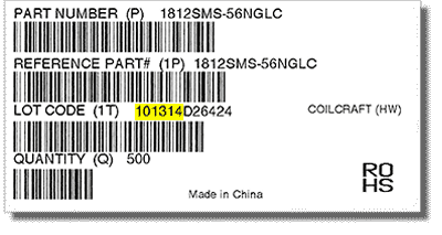
Coilcraft reel labels contain a manufacturing date code embedded in the first six characters of the "LOT CODE" field.

The date is in MMDDYY format. In the example below, the code 101314 = October 13, 2014.

datecode.gif

Dash numbers

What is a dash number?
A dash number is typically a three-digit code that corresponds to the three numbers that follow the dash in a part number. This code refers to the value in nanoHenries, where the first two digits are the value and the last digit is the multiplier (10^x) or number of zeroes that follow.

Therefore, 103 would be 10 × 10^3 (or 10 followed by three zeroes), which equals 10,000 nH, equivalent to 10 µH.

Other examples:
  • -394 = 39 × 10^4 = 390000 = 390,000 nH = 390 µH
  • -102 = 10 × 10^2 = 1000 = 1000 nH = 1.0 µH
  • -501 = 50 × 10^1 = 500 = 500 nH = 0.5 µH

Discontinued / Obsolescence / EOL / PCN / PDN

Are third party classifications of Coilcraft EOL and product life cycle accurate?
Many customers have shared with us inaccurate information regarding Coilcraft EOL and product life cycle predictions from online tools such as SiliconExpert. Coilcraft frequently supports products for many decades, and third party online predictors may fail to recognize this. Never trust EOL or product life cycle information about Coilcraft products unless the information comes directly from Coilcraft. 
Some of your parts are marked "Discontinued."

While Coilcraft has discontinued a small number of series, we will, when feasible, continue to support existing customers with previous order history for this series. For many of these parts, we have developed a newer series that surpasses the performance of the discontinued part. If you search for the discontinued part on our site, you will be guided to the replacement part.

Coilcraft can notify your company when products that you purchase are changed (Product Change Notice) or discontinued (Product Discontinuation Notice). Sign up for PCN and PDN emails here.

A number of your parts are designated as "Not recommended for new designs." Does this mean that I won't be able to buy these parts again?
For these series, we will continue to support existing customers with previous order history of the NRND part.
We used to buy 20% tolerance chip inductors from Coilcraft. Why are they no longer available?
Manufacturing processes have consistently improved, and all of our ceramic chip inductors now fall into the 5% or better tolerance range. These parts are an improvement of the parts you used to buy.

ESD (Electrostatic discharge)

Do you perform ESD testing on your components?
Coilcraft performs ESD testing per AEC-Q200 standards on all of our AEC-qualified products.

Export Control Classification Number (ECCN)

Where can I find the ECCN for your parts?
Coilcraft components are subject to the Export Administration Regulations (EAR), but the parts are not listed with a specific Export Control Classification Number (ECCN) on the Commerce Control List (CCL). EAR99 items generally consist of low-technology consumer goods and do not require a license in many situations. However, if the proposed export of an EAR99 item is to an embargoed country, or to an end-user of concern or in support of a prohibited end-use, a license may be required.

Effects of Ground Plane or Substrate

How can I predict the changes in inductance, Q and SRF when mounting your RF inductors over a ground plane or on various substrates?
Modelithics has measured many Coilcraft RF inductor series with a variety of substrate types and thicknesses. They have created global models that scale the substrate-sensitive parasitics for accurate simulations. View their models at: http://www.modelithics.com/mvp/coilcraft/.

The effects of ground plane proximity depend on inductor geometry and test frequency, along with substrate thickness and dielectric constant. In many cases, the effect is small, but it can be significant in very tight-tolerance applications. The interaction of the magnetic field of an inductor with a metal ground plane is a complicated 3D E/M problem that requires careful measurement or simulation under specific application conditions. For this reason, Coilcraft cannot quantify these effects in general.

Inductance of transformer secondaries

Transformer data sheets don’t specify the inductance of the secondary winding. Could you please provide it?
We do not provide a specification for transformer secondary inductance. However, you can calculate it as primary inductance times the square of the turns ratio. For example, for a 2:1 transformer with a primary inductance of 10 µH, the inductance of the secondary is 10 µH × (0.5)^2 = 2.5 µH.

Junction temperature

Why don't you specify the junction temperature on any of your data sheets?
Theta JA, Theta JC, Rja and Rjb are terms applicable only to active devices, such as integrated circuits. Inductors and transformers do not contain semiconductor material junctions and, so, do not have the same potential failure modes. Theta JA and Theta JC are therefore not applicable to inductors and transformers. See below for a discussion of thermal resistance.

Lead free / RoHS

Are all Coilcraft parts lead free?
Almost all of our parts are RoHS compliant, but not necessarily lead free. Any lead present in our RoHS-compliant parts is within allowed limits or is explicitly exempt in the RoHS directive.
Please read Coilcraft RoHS policy.

Medical, military and aerospace qualified

Are any Coilcraft parts qualified for medical, military or aerospace applications?
Coilcraft's Critical Products and Services Group offers products designed and tested specifically for these applications. Address your needs in an email to [email protected], or fax quote requests to 1-847-639-1508.

Moisture Sensitivity Level (MSL)

What is the Moisture Sensitivity Level of Coilcraft parts?
All Coilcraft components have a Moisture Sensitivity Level (MSL) of 1, indicating unlimited floor life at <30°C / 85% relative humidity. To be classified MSL Level 1, the component must pass the JEDEC J-STD-020 criteria of 168 hours in a chamber with 85°C / 85% relative humidity.

Non-magnetic products

My applications require the use of non-magnetic inductors. Which of your products are not magnetic?

All of our air-core inductors are non-magnetic:  Air-core Inductors
 
All of our all-ceramic core RF chip inductors are non-magnetic, with the exception of those with tin over nickel terminations. 
 
Non-magnetic ceramic series include CS, HP, HQ, PA, HC, CT, HS, and HT:  All-Ceramic Chip Inductors

Outgassing

Are there any outgassing issues with Coilcraft inductors?
There can be outgassing from any material under the right conditions. However, as a general rule, outgassing has not been reported with Coilcraft parts in commercial applications, and testing has not been required. For specialized applications where outgassing is a particular concern, we recommend you contact our Critical Products group for products that have passed NASA low outgassing specifications.

Packaging Options

What are my packaging options when ordering through Coilcraft customer service?

When ordering through Coilcraft customer service, you will be prompted to pick one of the following:

  • Cut Tape (can be two strips)
  • Continuous strip of cut tape 
  • Cover Tape extender ($5.00 per reel for less than full reel quantities)
  • Tape and Reel ($25.00 for less than full reel – Leader and Trailer added)
What are my packaging options when ordering from Coilcraft.com?

When ordering on the Coilcraft website, the default for less than a full reel will be “Ship in Cut tape (Change)”. Click Change  to select from the following:

A close-up of a roll of tape

Description automatically generated

Part marking / Color codes

I received parts with dot markings on them. Do the dots have a specific meaning?
Many Coilcraft chip inductors and some power inductors are marked with dots for identification. For an explanation of the color dots, please see RF Inductor Color Coding or Power Inductor Color Coding.
Your power inductors have numbers and letters on them. What is the “dash number” you refer to on your dimensional drawings? What do these numbers mean?
Part identification is specific to each product series. Refer to the part's data sheet for specific part identification markings. For very small parts, a marking may not be used; traceability to the original packaging information is required for accurate identification.

Power inductors, except for our smallest series, are commonly marked with a three-digit code that corresponds to the three numbers that follow the dash in the part number. This code refers to the value in nanoHenries, where the first two digits are the value and the last digit is the multiplier (10^x) or number of zeroes that follow. Therefore, 103 would be 10 × 10^3 (or 10 followed by three zeroes), which equals 10,000 nH, equivalent to 10 µH. Other examples:

  • -394 = 39 x 10^4 = 390000 = 390,000 nH = 390 µH
  • -102 = 10 x 10^2 = 1000 = 1000 nH = 1.0 µH
  • -501 = 50 x 10^1 = 500 = 500 nH = 0.5 µH

Part number codes

Are your part numbers and ordering options coded?
Coilcraft part numbers have evolved over many years. No single coding scheme applies to all products. Some characters may be placeholders. Most are fixed, but some may indicate ordering options. These codes may vary by product series. Our data sheets explain ordering option codes if any apply. Some part numbers may have meanings that are not defined, but these meanings are not necessary to understand. The specifications define the unique characteristics of any part number. Many of our part number characters have no specific meaning and are intended only to identify a unique product.

Below are two typical part-numbering schemes. Not all products follow these formats. 
Format 1: B0233-A or C0984-CL or M2022-ALPL
These are part numbers that have been created sequentially in time.
The -A and -C (or other -characters) may be a version of the specific part.
The "L" is one example of an additional character that has meaning only to Coilcraft.
Format 2: 1008CS‑100, 1008CS‑100X, 1008CS-100XJ, 1008CS‑100XJL or 1008CS‑100XJLC
Most often, characters before the dash represent a series designation, such as 1008CS. Series designations typically have four to seven characters. The dash followed by three digits, such as -100, represents an inductance value (see Dash Numbers).

The letter "X" is sometimes used as a placeholder for Coilcraft internal purposes. Other placeholder characters may be used. Characters following the dash may include tolerance codes, termination codes, packaging codes, testing codes, or other codes. Sometimes these are fixed characters for the series. In other cases, they may represent ordering options. These options are listed on our data sheets.

Polarity

Why don't you provide polarity markings on all of your parts?
Unlike capacitors or diodes, inductors do not have a functional polarity, and they work equally in either direction. Therefore, polarity is not important in the vast majority of end-use circuits. On rare occasions, it has been reported that some inductors perform better when mounted in one particular orientation, due to interaction with nearby components or ground plane conductors. Any asymmetrical performance is very much a function of the application, especially board layout. For further comments on board layout, see our sections on part spacing (minimum recommended inductor spacing) and shielding. For any applications in which inductor polarity is critical, please contact Coilcraft.

Potting / Conformal coating / Encapsulating

Can Coilcraft parts be potted?
While many Coilcraft parts may be potted, it is difficult to generalize about the possible effects of potting or coating. Potential considerations include differing thermal expansion coefficients of the potting compound vs. the inductor materials and changes in overall inductance and capacitance of the potted component vs. the original component.

Coilcraft does not test the effects of conformal coating. We recommend testing your specific material, process, and application conditions to determine the effects of any proposed potting material.

Power ratings

What are the power ratings for your inductors? They are not specified on your datasheets.

The reason that we don't specify power ratings for our inductors is that the more meaningful rating is the rms current rating. Inductor rms current ratings are derived by applying dc or low frequency ac current and measuring the resultant temperature rise. This allows for an accurate determination of temperature rise vs. rms current, which can easily be related to temperature rise vs. power loss: Power Loss = Irms2 × DCR.

In practice, inductor losses can include high-frequency core loss, skin effect and proximity effect, which can add to the temperature rise. While these losses are application-dependent and should be verified in situ, Coilcraft offers tools for predicting frequency effects. To estimate core loss, conductor loss, and temperature rise of our power inductors, use the Core & Winding Loss Calculator.

ESR vs. frequency for chip inductors can be graphed using the RF Inductor Comparison Tool.

Ratings (Inductance, Q, DCR, SRF, Current, Voltage, Temperature)

Do you have any documents describing the electrical specifications on your datasheets and how they are tested?

Returns

Can Coilcraft products be returned?
Coilcraft standard products can be returned within thirty (30) days of receipt of product by contacting our Customer Service Department for a Return Material Authorization (RMA). Returned merchandise must be in the original packaging and conform to minimum package requirements. Returned merchandise may be subject to a restocking fee. However, custom-made parts and/or CPS components cannot be canceled or returned.

Safety agency approvals

Can you provide UL and other safety organizations' approvals for your products?
Coilcraft products are typically not certified by UL, CSA, TUV, CE or other agencies. Safety standard listings most commonly apply to complete electronic assemblies, such as power supplies, computers, modems, or televisions, and not specifically to the high-frequency transformers or inductors that Coilcraft manufactures. In most cases, Coilcraft products are evaluated as part of the end equipment built by our customers; the inductors or transformers are not usually individually listed.

Upon customer request, Coilcraft may obtain specific transformer listings, for example, per UL / IEC 60950 Harmonized Standard for “Safety of Information Technology Equipment.” However, doing so will not automatically qualify the end equipment for agency approval. The manufacturer still has to submit the entire product to UL for approval. Alternatively, Coilcraft can supply certain pertinent information about Hi Pot voltages and insulation to support customers with the approval process when requested.

Some Coilcraft parts are designed to meet specific UL / CSA / IEC or other standards, as noted on the particular Coilcraft datasheet.

For more information or further assistance, please contact technical support.

Selecting the best part

Can you help me choose the right inductor or transformer for my application?

Yes, we provide many web-based tools and application notes to help you select the correct part.

Design Support Tools page Quickly zero in on the optimal part with these easy-to-use tools.

RF inductor finder Find every RF inductor that meets your specific requirements.

Power inductor finder View a sortable list of products that fit your application.

Converter inductor selector Input your parameters and get detailed inductor specifications.

Flyback transformer selector View a structured list of Coilcraft off-the-shelf flyback transformers.

We also provide cross references to IC applications and competitor parts:

IC / Inductor matching tool  Get a list of Coilcraft parts suitable for 1000s of IC reference designs.

Contact us for help finding Coilcraft alternatives to other manufacturers’ part numbers.

Our Application Notes page contains valuable information for selecting the right component for many applications.

How do I select the appropriate parts for my EMI / RFI filter application?
These three application notes contain in-depth discussions:
Common Mode Filter Design GuideCommon Mode Filter Inductor Analysis and Data Line Filtering.
I need a coupled inductor for a SEPIC application. Do you have any guidelines for selecting one?
The design procedure is explained in Selecting Coupled Inductors for SEPIC Applications.
You don’t have an off-the-shelf transformer that exactly meets the requirements of my application. Can you provide some guidance to use one of your standard transformers in my application?
You can adapt many of our transformers to a variety of circuit uses, by considering different connections for the windings. However, there are many variables to consider when adapting a component designed for one application for use in a different one. Review the application note Using Standard Transformers in Multiple Applications to determine if one of our off-the-shelf products would work for you.

Shelf life

What is the shelf life of Coilcraft's parts?
For 30°C / 85% relative humidity maximum, our parts are good indefinitely, whether in or out of packaging (based on MSL=1).

For uncontrolled or unknown environments, our parts are good for one year in packaging.
For uncontrolled or unknown environments, our shelf or floor life cannot be certified out of packaging.

Shielding

What's the advantage of using shielded parts?
The purpose of magnetic shielding is to reduce the amount of magnetic flux generated outside the inductor, in turn reducing the likelihood of radiating energy to nearby components or circuit board traces causing electro-magnetic interference (EMI). Whether a shield is necessary depends on the proximity of other components and how field interaction would affect the circuit's performance. Field interactions are challenging to model, and measurement of the final circuit design is recommended. In addition to reducing radiated fields, magnetic shielding typically contributes to the inductance of the component, helping to achieve more inductance per given size of inductor.

Soldering

Can Coilcraft parts be hand soldered?
Most through-hole parts can easily be hand soldered. While our surface mount parts are designed to be reflow soldered, many may be soldered by hand. We do not recommend attempting to hand solder our small chip inductors. Refer to our application note Soldering Surface Mount Components for a detailed discussion.
Can I use tin-lead solder with your RoHS-compliant parts?
You can solder Coilcraft RoHS parts using lead-based solders. As with soldering with lead-free solder, many factors influence solder wetting: solder amount, flux, temperature limit of each soldered component, heat transfer characteristics of the circuit board and component materials, and the layout of all components. Details
Can you provide a reflow soldering profile for your parts?
The optimal reflow profile for a circuit board assembly depends on the solder material, solder amount, flux, temperature limit of each soldered component, heat transfer characteristics of the circuit board and component materials, and the layout of all components. Therefore, there is no set profile for any of our parts. Refer to our soldering guidelines for a detailed discussion.

Spacing / Board layout

How much space should be allowed between components to counter interactions?
It is not feasible for Coilcraft to recommend a specific minimum spacing between inductors. Electromagnetic fields created by inductors generally interact only with metallic surfaces or other inductors in close proximity. However, the extent of interaction between inductors depends on the current (magnitude, waveform shape and frequency), the orientation to each other, and the distance between inductors. (Tip: Orienting the axes of inductors perpendicular to each other, rather than parallel, helps to minimize interaction.) 

Tape and reel

According to your datasheet, I can order my parts on a machine-ready reel, or in tape, but not machine ready. What is the difference?
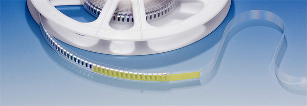
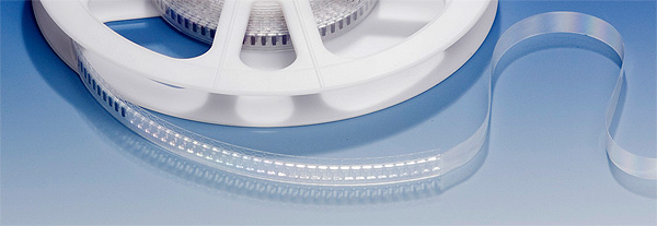
A machine-ready reel has a 400-mm leader of cover tape that includes 100 mm of empty sealed pockets and a 160-mm trailer of empty pockets sealed with cover tape. The leader is used to thread the tape through your pick-and-place machine. When you purchase a full reel of parts, the reel comes machine ready. If you purchase less than a full reel, the parts come in tape on a reel, but the tape does not have the leader or trailer. A leader and trailer can be added for an additional cost. A cover tape extender can be ordered for a nominal cost.
 
leader_cover_tape.jpg

$5.00 per reel    Cover tape extender (no empty pockets or trailer)

leader_eia.jpg

$25.00 per reel   Leader and trailer added

Where can I find tape-and-reel specifications for all of your products?
Tape-and-reel information is included on each product datasheet and with the dimensions for the product on the website.

Thermal resistance

Why don't you specify thermal resistance for your products?

Thermal resistance is not specified for Coilcraft inductors and transformers because they are mostly open-frame style and not solid, homogeneous bodies like molded IC packages. These body styles have a variety of thermal flow paths and multiple heat sources (winding and core), as opposed to an IC that may generate heat in a specific junction and conduct heat consistently throughout a solid body.

To calculate an approximate thermal resistance, divide the temperature rise due to Irms current (e.g., 40°C rise) by the power required to generate that rise (Power = DCR × Irms2) .

Rth (in °C/W) = 40°C ÷ (DCR × Irms2) where DCR is in Ohms and Irms is in Amps.

Tin whiskers

What tin whisker mitigation techniques are used on Coilcraft products?
Where tin is used in terminations, Coilcraft applies one or more of the tin whisker mitigation techniques described in iNEMI Recommendations on Lead-Free Finishes for Components Used in High-Reliability Products Version 4 (12-1-06).

Weight

Where can I find the weight for each of your parts?
The weight of a Coilcraft part is typically specified on the datasheet. In the case of a part series, a weight range may be given that covers the entire series.