站点设定

仓库
语言设定
货币设定
资源
视频库
Cx Family Common Mode Chokes
0402CT Low Profile Chip Inductors
XAL7050 High-inductance Shielded Power Inductors
XGL4020 Ultra-low DCR Power Inductors

Transponder Coils in an RFID System

Radio Frequency Identification (RFID) is the system of using radio signals to send information identifying a particular situation or item. It can be used to track and locate any item including material, people and animals.

There are two major components in an RFID system.
  1. The tag (transponder) programmed with unique information
  2. The reader (interrogator) includes a decoder to interpret data.
The tag consists of an integrated circuit and a coupling device. The integrated circuit stores specific data unique to that tag. The coupling device interfaces with the reader.

The RFID transponder coil is part of the coupling device and acts as the transmitting antenna. The key specifications of the transponder coil are sensitivity and read distance, however, the inductance of the transponder coil directly influences the sensitivity and the read distance. Generally, a higher inductance provides greater sensitivity resulting in a longer read distance. The manufacturer of the tag usually specifies the inductance of the coil to be used. The read distance is defined as the maximum distance from the reader that the transponder responds to the reader’s magnetic field.

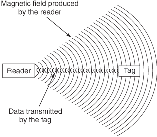
Refer to Figure 1. The reader produces a magnetic field that triggers the tag. When the reader receives the transmitted data, it interprets the data and takes appropriate action. When the transponder enters the field produced by the reader, the coil produces a voltage inside the tag. In a passive transponder, this voltage can be used to power the tag. In an active transponder, the voltage is used to wake the tag and use its internal battery. Active transponders generally have longer read distances, shorter operational life and are larger and more costly to manufacture. Passive transponders are generally smaller, have a longer life and are less expensive to manufacture.
 
Doc397-Fig1-Basics.gif
Figure 1. RFID System

For optimum performance, the transponder coil is used in a parallel LC circuit as shown in Figure 2. Adding a capacitor to the circuit maximizes the read distance. The LC circuit is designed to resonate at the operating frequency of the reader.
 
Doc397-Fig2-LC-Schematic.gif
Figure 2. LC Circuit

Use the following equation to calculate the value of the capacitor.

Doc397-LC-Calc1.gif

Example:
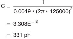
Calculate the capacitor value for a 4.9 mH transponder coil operating at 125 kHz

Doc397-LC-Calc2.gif

Coilcraft transponder coils are wirewound, surface mount antennas designed for use in a 125 kHz RFID system. They are rated for 125°C operation.
Doc 397

Questions or Concerns?

Ask View FAQs


General Applications

Handling and Processing

RF Inductors

Power Conversion

EMI/RFI Filtering

Special Applications