站点设定

仓库
语言设定
货币设定
资源
视频库
Cx Family Common Mode Chokes
0402CT Low Profile Chip Inductors
XAL7050 High-inductance Shielded Power Inductors
XGL4020 Ultra-low DCR Power Inductors

Signal Transformer Application

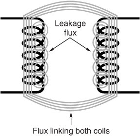
In the simplest sense, a transformer is two or more windings coupled by a common magnetic field. This magnetic field provides the means to pass voltages and currents from one winding (primary) to the other winding (secondary). Magnetic flux is created when an alternating current flows through a winding (see Figure 1).
 
Doc157-Figure1.gif
Figure 1

The magnetic field (represented by magnetic flux lines) follows the path of least magnetic resistance (reluctance). Not all of the flux created by the first winding flows through the second winding. Leakage flux is the flux that does not connect the two windings and results in lost energy. There are other forms of energy losses such as core and winding losses that also reduce the efficiency of the transformer but they will not be discussed in detail here. One way of reducing the amount of leakage flux is to shorten the path between the two windings or to place the windings on top of each other. Properly configuring the windings allows more of the flux to link both windings and limits losses. Lowering leakage flux (leakage inductance) is a primary goal of the signal transformer designer since fewer losses means that a greater amount of the signal will be transferred in an undistorted manner.

Transformer have many uses, such as isolation of DC currents, voltage and current transformations, and impedance matching. The type of signals to be transferred from the primary to secondary windings dictate the type of transformer that should be used in an application. For instance, a transformer needed to provide DC isolation between two windings carrying large amounts of currents would be designed differently from a transformer that needs to provide an impedance match to a small signal communications network. In this article, the emphasis will be on two types of signal transformers that are designed specifically for the transmission of data at low power levels with DC isolation (the wideband transformer) and those designed to be non-isolating (the auto transformer). These types of transformers are not limited to low power capabilities, but the emphasis here is for use in communication and small signal applications.

The Wideband Transformer

Many transformers are efficient in their ability to carry large amounts of voltage and current over a narrow range of frequencies. However, transformers are inefficient in transferring energy if they distort the signal. A wideband transformer can transmit a clean, undistorted low-power signal over a wide range of frequencies. This is important when transmitting signals such as square waves because each individual pulse is made up of a wide range of harmonics. These harmonics give the square wave its shape and are necessary to preserving the original wave shape.

Wideband transformers can be used for many different applications including: DC isolation between circuits, impedance matching, phase shifting, coupling, balanced to unbalanced transitions, and current and voltage conversion. The significance of a wideband transformer is that it can transmit small signal information over a wide range of frequencies. Wide bandwidths are possible through tight coupling between the primary and secondary windings.

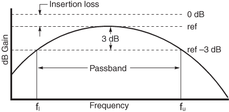
The operable range of frequencies for a wideband transformer is referred to as the bandwidth. The bandwidth is the range of frequencies that is allowed to pass while still maintaining at least half of the signal power. The half power point is specified as being 3 dB down from the insertion loss (see Figure 2).

Other parameters also need to be considered when evaluating a wideband transformer. Depending on the application, the maximum or minimum inductance of the primary or secondary winding, DC resistance of the windings, rise time, or a number of other factors might be considered. One primary parameter that needs to be determined is the turns or inductance ratio. The ratio is used for matching the primary and secondary impedance of the transformer to the circuit into which it is inserted. This ratio is also crucial for “stepping up” or “stepping down” a voltage or current from one side of the transformer to the other.
 
Doc157-figure-2-passband.gif
Figure 2

Design Equations

Wideband transformers are often used to step-up or stepdown voltages or currents. The same techniques can be applied to matching impedances between unbalanced circuits.
 
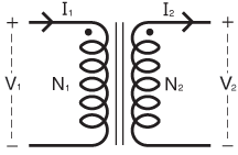
Doc157-Figure3.gif
Figure 3

For the purpose of design simplicity, a lossless transformer will be used to derive the equations (see Figure 3). For a lossless transformer, the following equations are true:
 
N1 N2 =  V1 V2 =  I2  I1 = a
Where:
N1 = number of turns on primary
N2 = number of turns on secondary
V1 = voltage across primary
V2 = voltage across secondary
I1 = current through primary
I2 = current through secondary
a = turns ratio

The inductance of a winding can be approximated by using the following relation:
L = N2AL
where AL is the equivalent inductance (per turns squared) of the core material. This is generally specified by the core manufacturer.

To find the required turns ratio necessary to match two impedances Z1 and Z2, the following relations are used:
 
ZV1I1  = V2I2  (a2) = Z(a2)   where  N1 N2  2= a2

Note that the impedance is proportional to the square of the turns. For example, if a 100 Ohm source Z1 is to be connected to a 150 Ohm load Z2, the resulting turns ratio necessary would be:
100 = 150a2               100150   = a           a ≃ 0.816
therefore   N1 = 0.816N2

The Autotransformer

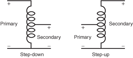
Another type of transformer that is used in communication systems is the autotransformer. The autotransformer has its own unique characteristics while sharing many of the benefits of the wideband transformer. It can be used in many of the same applications as the wideband transformer such as voltage dividers, impedance matching, phase shifting, and voltage and current transformations. It cannot, however, provide any DC isolation between the primary and secondary(s). What the autotransformer lacks in DC isolation, it gains in efficiency, lower leakage inductance, and better voltage regulation. A step-down and a step-up autotransformer are shown in Figure 4.
 
Doc157-Figure4.gif
Figure 4

The autotransformer is ideal when DC isolation is not necessary and optimum efficiency is needed. Additional efficiency is gained by way of greater coupling, which in turn, leads to less leakage inductance. This is partially due to the autotransformer passing part of the energy from primary to secondary by voltage division. The wideband transformer delivers all of its energy by transformer action. The autotransformer delivers part of the energy directly through the winding and the other part through means of a magnetic medium, allowing for better coupling between the primary and secondary and thus less leakage inductance and increased bandwidth.

An autotransformer also requires fewer windings to achieve the same result as an isolation transformer. This is due to the secondary using part of the primary winding to achieve the necessary turn count for a step-up or step-down transformer (see Figure 4). Since fewer turns are needed to achieve the same primary to secondary impedance ratio, total copper loss is reduced making the autotransformer more efficient than a comparable wideband transformer. The autotransformer is not limited to a single secondary (or “tap”), but may have multiple taps off of the primary winding.

Design Equations

The techniques used in determining the appropriate number of turns to step-up or step-down a voltage, or match impedances is similar to that of the isolation wideband transformer.
 
Doc157-Figure5.gif
Figure 5
 
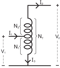
For an autotransformer (see Figure 5), the following equations should be used:
 
N1NT  = N1N1+ N2  = V1V2  = I2I1   = a

I3 = I1 - I2
Where:
N1 = number of turns common to primary
N2 = number of turns common to secondary
NT = N1 + N2 = total number of turns
V1 = voltage across primary
V2 = voltage across secondary
I1 = current in tap
I2 = current in N2 winding
I3 = current in N1 winding
a = turns ratio = N1/ NT

The inductance of a winding can be approximated by using the following relation:
L=N2AL
where AL is the equivalent inductance (per turns squared) of the core material. This is generally specified by the core manufacturer.

To use the autotransformer as a voltage divider network, use the following equation:
V(N1+N2N1 )V1

To use the autotransformer as an impedance matching network, use the following equations:
Z1 = V1I1   = V2I2 (a)= Z2(a)2
where    a = N1NT  = N1N+ N2
therefore    N(1 - aa )N1
 
For example, if a 100 Ohm source Z1 is to be connected to a 150 Ohm load Z2, the resulting turns ratio necessary would be:
 
100 = 150a2               a = 100150             a ≃ 0.816
therefore     N1 = 0.816NT
N2 = N- N1
N(1 0.816 - 1)N1
N2 = 0.225N1

Conclusion

The basic design and application of the wideband transformer and autotransformer has been covered. It can be used as a guide when specifying a Coilcraft wideband transformer and autotransformer. Please contact your local Coilcraft representative for information regarding standard and custom versions.

Bibliography

Guru, Bhag S. and Hiziroglu, Huseyin R., “Electric Machinery and Transformers” (Harcourt Brace Jovanovich, 1988)
Hunt, William T. Jr. and Stein, Robert, “Static Electromagnetic Devices” (Boston: Allyn and Bacon, 1963)
Snelling, E.C., “Soft Ferrites - Properties and Applications, Second Edition” (Butterworth and Co., 1988)
Grossner, Nathan R., “Transformers for Electronic Circuits, Second Edition” (McGraw-Hill, 1983)
Doc 157

Questions or Concerns?

Ask View FAQs


General Applications

Handling and Processing

RF Inductors

Power Conversion

EMI/RFI Filtering

Special Applications