站点设定

仓库
语言设定
货币设定
资源
视频库
Cx Family Common Mode Chokes
0402CT Low Profile Chip Inductors
XAL7050 High-inductance Shielded Power Inductors
XGL4020 Ultra-low DCR Power Inductors

Selecting Coupled Inductors for SEPIC Applications

Application Design Example

The SEPIC (Single-Ended Primary Inductance Converter) topology is used in applications that require characteristics of both a buck and a boost regulator, specifically the ability to step up and step down the input voltage. Most often operated in CCM (Continuous Conduction Mode), SEPIC provides a non-inverted output voltage.

Typically, SEPIC is used in battery operated systems and automotive applications. In these applications, the battery input voltage, or bus line voltage, may be greater or less than that of the desired output voltage, depending on the charge state of the battery. The SEPIC topology can operate over more of the battery discharge cycle because of the ability to regulate the output voltage over a wider input voltage range, including above and below the output voltage.

A simplified SEPIC schematic, using coupled inductors is shown in Figure 1.

Doc639-Fig1-Sepic-schematic.gif

Figure 1. Simplified SEPIC Circuit Diagram

C1: Flying capacitor – Should be low ESR, most often ceramic.

C2: Output capacitor – Chosen based on output ripple current tolerances, usually tantalum.

L1 and L2: Coupled inductor – Two inductors closely coupled on a common core.

Inductors L1 and L2 do not have to be wound together on a single magnetic core, however there are distinct advantages if they are. If L1 and L2 are closely coupled, the ripple current is divided between them and the required inductance is halved. For example, two 22 µH single inductors can be replaced with one coupled inductor of 11 µH per winding, potentially allowing for the selection of a smaller inductor, or one the same size that has lower DCR and higher current handling.

The selection of one coupled inductor over two single parts saves board space and can also save cost.

The following examples demonstrate the calculations necessary to identify the inductance, rms current and peak current ratings.

Coupled Inductor Calculation

Assume the following parameters for the circuit shown in Figure 1:

VIN = 2.7 V to 4.5 V
VOUT, IOUT = 3.3 V, 0.2 A
Fs (Switching Frequency) = 400 kHz
VD1 (Typical Voltage Drop) = 0.7 V

Target Efficiency = 90%

Step 1. Calculate minimum and maximum duty cycle (Dmin and Dmax)


Doc639-Sepic-equations(1).gif


Step 2. Calculate peak to peak ripple current

The allowed ripple current percentage must be chosen. A good starting point is to limit the peak to peak ripple current to 40% of the full load inductor Irms current. This ensures a low output ripple, minimizes core loss in the inductor and allows for light load continuous conduction mode operation to current as low as 20% of full load.

Allowing for 40% ripple, calculate the worst case peak to peak ripple current at VIN(min) using the following equation:


Doc639-Sepic-equations(2).gif


Step 3. Calculate inductance

Inductance is calculated by the fundamental equation:


Doc639-Sepic-equations(3).gif

Because the two windings of a coupled inductor share the ripple current, the inductance value can be halved.


Doc639-Sepic-equations(4).gif


Choose standard value L = 22 µH

Step 4. Calculate required Irms


Doc639-Sepic-equations(5).gif


Step 5. Calculate Ipeak


Doc639-Sepic-equations(6).gif


Step 6. Summarize inductor specifications

L1 = L2 = 22 µH
Irms (L1) = 0.27 A
Ipeak (L1) = 0.32 A
Irms (L2) = 0.20 A
Ipeak (L2) = 0.25 A

Step 7. Select the coupled inductor

Choose Coilcraft LPD4012-223ML.

Coilcraft LPD4012-223ML has 22 µH per winding, and a saturation rating of 0.70 A. This means that 0.35 A per winding (or any combination that does not exceed 0.70 A) can flow without saturation.

Coilcraft LPD4012-223ML has Irms rating of 0.34 A for both windings and 0.48 A for a single winding. This means that for a 40°C temperature rise, up to 0.34 A can flow in each winding simultaneously or up to 0.48 A can flow in one winding.

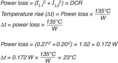
For this example, Irms of L1 (0.27 A) and Irms of L2 (0.20 A) are well below these limits. Refer to the LPD4012 data sheet, and use the following formulas to calculate the temperature rise (∆t):

Doc639-LPD4012_ex.gif

Step 8. Frequency Dependent Losses

In most cases the I2R loss calculated in Step 7 provides a good estimate of the inductor losses. However, frequency dependent losses such as core loss and ac winding loss should also be considered.

To estimate total inductor loss including ac winding resistance and core loss refer to the Coilcraft Coupled Inductor Finder and Analyzer tool at www.coilcraft.com/ en-us/tools/coupled-inductor-finder/#/search.

Calculate the Total inductor loss for each winding. To determine temperature rise, add the Total inductor loss for each winding together, and multiply this number by 135 as shown in step 7.

References

Designing a SEPIC Converter, Wei Gu, National Semiconductor Application Note AN1484, June 2007

Versatile Low Power SEPIC Converter Accepts Wide Input Voltage Range, Jack Palczynski, Unitrode Design Note DN-48.

SEPIC Equations and Component Ratings, Maxim Integrated

Doc 639

Questions or Concerns?

Ask View FAQs


General Applications

Handling and Processing

RF Inductors

Power Conversion

EMI/RFI Filtering

Special Applications