站点设定

仓库
语言设定
货币设定
资源
视频库
Cx Family Common Mode Chokes
0402CT Low Profile Chip Inductors
XAL7050 High-inductance Shielded Power Inductors
XGL4020 Ultra-low DCR Power Inductors

Getting Started: An Introduction to Inductor Specifications

Inductance is just one criteria for selecting the right inductor

There is more to selecting an inductor than the nominal inductance value. To ensure the inductor will perform as needed in a specific application, due consideration must be given to inductance tolerance, current ratings, DCR, maximum operating temperature and efficiency at specific operating conditions. Even the inductance value needs careful consideration, as inductance itself is dependent on frequency, temperature, and current.

Inductance at Frequency

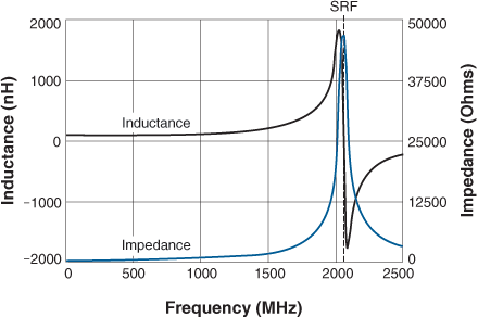
The physical embodiment of any inductor includes parasitic R, C, and L elements to varying degrees, resulting in a non-ideal inductive element. A major parasitic element that directly impacts the inductor performance is capacitance, which combines with the nominal inductance to form a resonant tank circuit. Figure 1 shows inductance vs frequency for a typical inductor. The apparent inductance increases to a peak, and becomes zero at the natural selfresonant frequency of the inductor. While the inductance itself does not really increase in this manner, what the graph shows is the apparent inductance as measured on a typical L-C-R meter. Generally, unless they are being used as chokes, inductors are selected to avoid operation in the frequency region near the self-resonant frequency.

When selecting an inductor for any application it is crucial to understand what test frequency was used to arrive at the data sheet specification.
Doc1287-fig1.gif
Figure 1. Inductance and Impedance for a 100 nH Wirewound Inductor

Inductance Tolerance

A power inductor selected for smoothing out the ripple current in the output of a DC-DC power supply might be specified with a ±20% inductance tolerance. That’s generally the tolerance at room temperature, and since inductance typically decreases with decreasing temperature, the actual inductance seen by such a circuit could be outside that tolerance, depending on the temperature. Careful consideration should be given to understanding the inductance change over the expected operating temperature range.

Manufacturer specified tolerances can vary widely, depending on the type of inductor and its intended application. Chip inductor specifications, for example, can be as tight as ±1% at room temperature. That’s very appropriate for high frequency, narrow-band tuned circuits, but it must be considered that the 1% inductance tolerance is specified only at room temperature and the specific test frequency. Typical wire-wound air core and ceramic core chip inductors (non-magnetic) have a temperature coefficient of inductance (TCL) in the range of +25 to +125 ppm/°C. Inductors with ferrite cores will have more variation, with temperature, with TCLs up to 700 ppm/°C or higher.

Current Ratings

The Irms current rating is an indirect measure of inductor temperature rise to be expected from a given amount of power dissipation. This rating represents two factors: how much power dissipation is caused by inductor current and, how much temperature rise results from that power dissipation.

Irms current ratings are generally derived from measuring inductor temperature rise due to current flow without consideration of frequency effects. The Irms rating is not intended to capture all possible forms of power loss due to application conditions. The power dissipation is simply = I2R, where R is the dc resistance of the wire winding and I is the average or dc value of the inductor current.

Since Irms is a measure of self-heating, the limitation is generally the temperature rating of the insulating materials in the inductor. Therefore the Irms rating is a measure of how much current may be allowed in the inductor to ensure safe, reliable operation without heat damage to the inductor.

Calculating losses with frequency effects is not always straightforward, depending on many factors in both the winding and inductor core. To quantify the impact of operating frequency, inductor manufacturers provide a variety of graphs, charts and calculator tools to determine the impact of skin effect, proximity effect, and magnetic core losses.

For example, the RF Inductor/Choke Finder and Analyzer generates ESR vs frequency curves for chip and air core inductors. The Power Inductor Finder and Analyzer provides a measure of core and winding losses for power inductors.

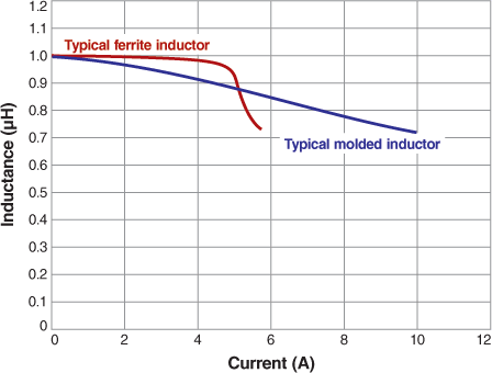
Isat current rating is a different consideration. Whereas the Irms rating deals with heat rise and reliability due to average inductor current, the Isat rating is a performance indicator related to the instantaneous inductor current. Ferrite core inductors, for example, tend to have very flat inductance vs current curves until the “knee” where inductance drops off rapidly, as shown in Figure 2. Powdered iron or composite core inductors have more slowly sloping “soft” saturation curves. At current above the saturation current rating (Isat) inductance decreases with additional current. Typical data sheet specifications show the current at which the inductance drops 10%, 20%, and 30% of its initial value at low current.

Some inductor types with “open” magnetic paths such as unshielded rod core, drum core, or unshielded chip inductors may not have published Isat ratings because there are no meaningful saturation effects at currents as high as 2× or 3× the Irms current so the usable current is effectively limited by the Irms rating and it is assumed there is no saturation at currents at that higher level.
 
Doc1287-Figure2.gif
Figure 2: Saturation curve comparison between ferrite and powdered iron inductors

Maximum Operating Temperature

The maximum operating temperature is defined as the maximum temperature of the inductor under any combination of ambient (surrounding) temperature plus the self-heating temperature rise due to current.

An approximate thermal resistance can be calculated from the data sheet Irms rating.

Power dissipation: Pdc = Irms2 × DCR
so,                    Rth (in °C/W) = Temp Rise / Pdc.

Expected temperature rise can thus be calculated for any power dissipation, and the resulting part temperature can be compared to the maximum inductor temperature rating.

Losses at Operating Conditions

Inductor power loss is dependent on temperature, frequency, and both dc and ac current. Calculating allowable loss for a specific application condition can be complicated. Inductor data sheets may include ESR vs frequency information or equations for core loss calculations. Coilcraft Power Inductor Comparison + Analysis Tool provides this information for a wide range of user-specified operating conditions.

The Power Inductor Comparison + Analysis Tool allows users to compare up to six inductors for core and winding losses under any combination of operating frequency and current. The calculator estimates the resulting temperature rise (per the above calculations) and compares the resulting part temperature to the maximum part temperature rating. In the graphical results display, sliders can be manipulated to view how frequency, current, or ambient temperature affects the result. When searching for a specific power inductor for your application, The Coilcraft Power Inductor Finder tool incorporates all of these calculations and lists every inductor that meets the user specified conditions.

References

  1. How Current and Power Relates to Losses and Temperature Rise, Document 1055, Coilcraft, Inc., 09/04/2012
  2. RF Inductor Comparison Tool, Online Tool: RF Inductor/Choke Finder and Analyzer Coilcraft, Inc.
  3. Power Inductor Comparison + Analysis Tool, Online Tool: Power Inductor Finder and Analyzer
Doc 1287

Questions or Concerns?

Ask View FAQs


General Applications

Handling and Processing

RF Inductors

Power Conversion

EMI/RFI Filtering

Special Applications