站点设定

仓库
语言设定
货币设定
资源
视频库
Cx Family Common Mode Chokes
0402CT Low Profile Chip Inductors
XAL7050 High-inductance Shielded Power Inductors
XGL4020 Ultra-low DCR Power Inductors

Data Line Filtering

Introduction

Noise is a major concern among designers of electrical equipment because failure of an electronic design due to unexpected or indeterminate noise sources is not uncommon. The FCC and other regulatory agencies are rigorously enforcing their noise requirements and this gives noise an often pivotal role in the ultimate success of a piece of electronic equipment. This paper will address some of the important attributes of the noise associated with electrical and electronic equipment, particularly low signal level data line equipment of which digital equipment is one type. Some simple filtering solutions will also be discussed.

Noise Sources

Power converters are notorious sources of noise; they normally produce both common mode (occurring equally on all signal and common lines which refer to earth ground) and differential mode noise (occurring between signal and return paths). Noise from power converters generally predominates at the harmonics of the switching frequency, but some wide band noise is also produced. Because power converters are often required within electrical proximity of low signal level circuitry, they can be a major factor in determining the overall dependability of the data line system involved. Semiconductor devices may act as noise sources because of temperature (thermal noise), the adjoining of differing materials (contact noise), and the electron-hole movement of junction devices (shot noise). The magnetic components of modules which often support a data line system (for example, the transformer of a power converter, or some other high Q component) may themselves produce noise from ringing.

The logic circuits of equipment are yet another significant source of noise. At the switching of logic levels, the local power source can momentarily short to ground, introducing noise directly to both the ground plane and the dc power supply and affecting the entire electrical system.

Internal noise may be generated from a number of sources which are electrically near the data line circuitry such as adjacent printed circuit boards or local magnetics (transformers, mixers, etc.) Semiconductor noises can also propagate to the threshold sensitive logic lines, to and from digital system clocks, and onto data lines.

Externally created noise may emanate from a number of sources which are beyond design control. High frequency noise may appear on the power line, riding the 60 Hz signal usually without affecting the power circuitry, but providing a real danger to data line transmissions. Radiated noise may impinge on many parts of a piece of electronic equipment, especially through unshielded cabling, or through an ineffectively grounded case. Cabling is an important factor in the generation of EMI. Cables are generally the longest paths between circuit components and modules, thus providing an optimum situation for creating a loop antenna for radiating and receiving externally generated noise fields.

Noise Signal


Doc155-DRAWING1.gif

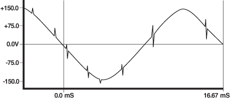
Figure 1. Line source in a factory

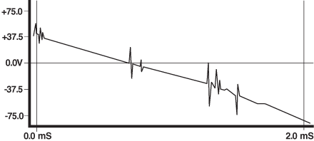
Figure 1 shows an actual sine wave of 60 Hz line voltage (110 Vrms) occurring in a typical factory situation. The waveform contains random noise voltages of much higher than line frequencies. Figure 2 shows a 2 mS section of the 60 Hz wave with noisy spikes shorter than 5 µS and attaining 50 V peaks. Much higher frequency noise can also exist beyond the resolution of the waveform plot.


Doc155-DRAWING2.gif

Figure 2. 2 mS section of the line

Contaminated line currents are conducted directly into machines and devices connected to the same line as the offending machines; noise voltages can also be measured radiating through the air near these machines.

Generally, line filters are placed ahead of sensitive equipment to improve the situation of the 50 V high frequency factory noise mentioned above. Typically, a line filter is composed of a low frequency common mode magnetic structure which allows (differential) line current to pass freely without saturating the magnetic material (differentially induced flux lines cancel one another; this is the primary aspect of a common mode magnetic design). However, the noise common to both the source and return lines is attenuated.


Doc155-DRAWING3.gif

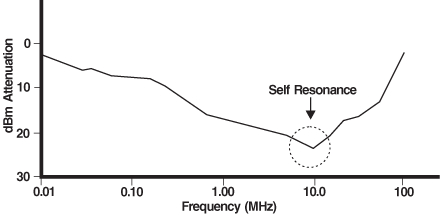
Figure 3. Typical line filter response

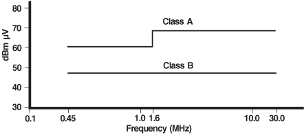
Line filters clean the incoming 60 Hz line signal by substantially attenuating frequencies through approximately 10 MHZ, with increasing failure to attenuate beyond this frequency (Figure 3). A real possibility still exists for higher frequency line aberrations, which often evade line filtering, to affect the integrity of the low voltage data transmission of data line equipment. Especially vulnerable is inter-equipment data transmission. An additional problem lies in the fact that equipment designated for factory use need only meet relatively less stringent noise requirements, although these machines have the potential for affecting their more sensitive counterparts (Figure 4).


Doc155-DRAWING4.gif

Figure 4. FCC noise limits

Certainly many data line devices and equipment are not intended to be situated in the severe environment of a factory. For example, the equipment required to meet FCC Class B limits do not usually have to deal with 50 V noise occurring from the power line; yet, Class B devices are becoming more and more susceptible to the usually low level/very high frequency noise common to contemporary data line equipment environment (Figure 4). Especially true is the sensitivity to noise of equipment which runs at high clock speeds and baud rates.

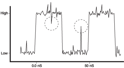
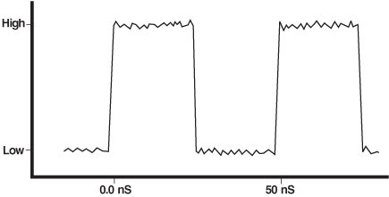
The system clocks of data line equipment are one concern of the noise conscious design engineer. Figure 5a shows a 20 MHZ clock signal with a spurious high frequency content and potential problem regions; Figure 5b shows a noise-free 20 MHZ clock signal.


Doc155-DRAWNG5A.gif

Figure 5a. 20 MHz clock with high frequency noise


Doc155-DRAWNG5B.gif

Figure 5b. A clean 20 MHz clock signal

The transmission of data between equipment, whether within a local networking scheme or machine-to-machine communication through peripheral equipment like modems, can be disrupted and contaminated by unchecked noise.

Filtering in General

The obvious solution to the problem of noise is to eliminate the source, but this is often out of the question. Noise emanating within a piece of equipment is almost always a side effect of a critical module of a design. The next obvious solution is to eliminate the noise at or as near the source as possible. Noise sources may sometimes be obvious. A power supply, for example, is a logical place to expect ample noise to emerge. Sometimes the sources of noise are not at all predictable; moreover, the precise effect of a noise source is often illusive and only sporadically evident. The achievable solution to the problem of noise is to prevent it from affecting the systems and subsystems susceptible to it. After locating and filtering the obviously culpable noisemakers (e.g., the output of a power supply), the next step is to protect the inputs to the sensitive equipment and components. No more noise is then permitted into the sensitive equipment than the equipment may continuously tolerate. By filtering the inputs of sensitive components, the elusive and unmanageable sources of noise then become much less critical to the operation of the equipment.


Doc155-DRAWNG6.gif

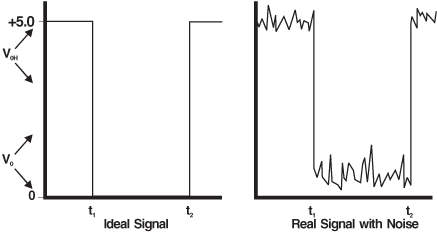
Figure 6. TTL signals

Filtering is the ready solution to the problem of noise. Digital equipment and sensitive components can be made to withstand the subtle noise emanating from subsystems of the equipment as well as its external environment. Conducted noise often creates external fields, radiating noise to equipment and components which in turn induce conducted noise into these equipment and components. Also, the higher the frequency the less energy required for disruption. The cabling used to relay data line signals is particularly sensitive to external noise, both conducted and radiated. Because data line signals are essentially square waves with predetermine transition levels (e.g., 0.8V and 2.0V for TTL, Figure 6), the sudden encroachment of a noise spike in the electrical vicinity of the cable, or radiating near the cable, could cause a data error at the receiving end of the cable.

Filtering Techniques

A noise spike is caused by transient energy of a high frequency content. Because noise spikes are composed of such high frequency energy, the drastic attenuation of all high frequency noise just prior to reception of a logic signal would preserve the integrity of the original signal. Likewise, attenuating all high frequency components of the signal just ahead of a transmission cable would clean up the signal affected by noise within the data line system itself prior to any transmission. Also, the logic levels of the digital clock must be precise and unadulterated. Clock signals can benefit from high frequency noise attenuation, safeguarding the data line system from false state and logic transitions.

Magnetic Filtering

The solution to EMI problems typically arising in cabling is inherently magnetic. Cables are loop antennas created by a miss-match of a cable’s signal and return line current. If the signal and return lines of a cabling scheme were positioned identically in space, the field created by the conducted current in the signal line would exactly cancel the field effected by the conducted current of the return line; of course this 180° perfect current reversal is not realizable, and we therefore must have a finite quantity of radiation due to any cabling.

Twisting signal and return lines of a cable where possible breaks up the loop antenna structure into smaller loop antennas, achieving two useful results: 1) a substantial increase in the resonant frequency of the generated/ received fields, and 2) allowing adjacent and inverted fields to cancel one another. Increasing the noise frequency is sometimes helpful, but generally not a sufficiently complete solution since applicable noise frequencies range into the hundreds of megahertz.

Ribbon type cabling usually does not lend itself to the twisting method described, unless special pre-twisted ribbon cabling is used (where the ribbon lines are twisted in pairs) but running return lines directly adjacent to respective signal lines is necessary to decrease radiated/ received noise. Determining the actual ribbon cable line assignments is seldom an option provided an EMI engineer; usually, a solution to noise problems is a post mortem activity, such basic layouts having already been made for an equipment’s design.

Filtering of a data line system, particularly when cabling and other signal wires are the objects to be safeguarded, is generally and most successfully realized through external magnetics. Creating a magnetic field around a wire can divert the high frequency energy from the signal propagating through the wire. By increasing the inductance of the wire or cable at an appropriate point along its path, a magnetic field can be created and magnified. Forming the cable or wire into a number of loops is the simplest method of increasing inductance. However, to obtain any useful inductance (thus appropriate attenuation of noise frequencies), many tens, or even hundreds, of loops would be required. Many loops are required to obtain the useful magnetic field because air alone is utilized to contain the field. Fortunately, magnetic materials can be used that have tens of thousands of times the magnetic capacity of air. Magnetic materials significantly increase the inductance with minimal looping of associated wires and cables.


Doc155-fig_7.gif

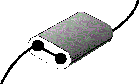
Figure 7. A binocular filter

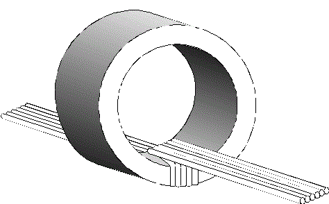
Magnetic beads are often utilized for filtering; binocular cores, often used in balance to unbalanced (“Balun” transformers) are also used in common mode filtering. A wire through one hole in a balun effectively constitutes a single turn (Figure 7). The advantage of using baluns is in their simplicity: one wire, one bead. Unfortunately, one bead may not suitably attenuate high frequency noise for many data line systems. Several beads may be strung together on the same wire for increased attenuation, but stringing beads on a signal wire, or multiple beads on a cable of multiple wires can result in both a difficult design and problems achieving repeatable design. Also, beads, each one magnetically isolated from all others, lack the ability to attenuate wide band common mode noise while supporting differential signals.

The problem of common mode noise is very real and somewhat elusive. Because it occurs equally and in phase on all signal lines with relationship to the ground plane, it becomes evident within an electronic system only when measured with reference to earth ground.


Doc155-fig_8.gif

Figure 8. Filtering with a large magnetic structure

Within a single piece of equipment, common mode noise, though very real, may be difficult to detect. The subsystems of a piece of electronic equipment, each with semi-isolated ground planes, may display symptoms of common mode noise, a loss of signal integrity and a failing electrical reference. Likewise, when isolated pieces of equipment, having independent common references, are used in conjunction with one another (e.g., communicating through common signal lines), the common mode noise from each can become problematic. Fairly large magnetic toroidal structures may be used in a similar manner to a bead for filtering cables by fitting the structure around the entire cable. (Figure 8). While using a single, large structure allows common mode noise attenuation, it may lack the magnetic capability to provide effective protection of cabling because of the physical limitation of looping the cable through the large toroid more than once (thus increasing inductance).

Another method of protecting a data line system from noise is the use of special cable connectors which are either predominately capacitive or magnetic by design. The protection thus provided is limited to external connections. The capacitive connectors are typically more expensive than equivalent magnetics; magnetic connectors often have the additional advantage of being common mode by design. Multi-line common mode components are also available. Such components are magnetic, are compatible with ribbon cabling, and can be readily designed into a circuit. These multi-line common mode “Data Line” filters are available in standard DIP and surface mount configurations.

Rules of Thumb

A successful filtering program of a data line system should have the following features:

  1. The filter method must provide for the maintenance of a signal integrity.
  2. The filter method should be able to increase substantially the magnetic field at virtually any critical electrical location.
  3. The filter method must provide effective attenuation of all high frequency noise, as well as broadband common mode noise.
  4. The filter method must be compatible with standard cabling schemes, including ribbon-type cables, and individual signal wires.
  5. Ideally, the filtering method should be easy to implement, readily available, and successfully repeatable.

Conclusion

Noise sources are prevalent in a number of environments. Particularly severe is the factory situation where high frequency/high level noise transients intrude onto the power mains. To a lesser degree, such noise also may be found in the power stage of a piece of sensitive equipment. Power converter noise may also be evident outside the factory situation, where the more stringent regulatory agency noise limits come into effect.

The various noises which can destroy the repeatability and integrity of sensitive equipment, particularly data line equipment, are essentially of two types: common mode and differential mode. Common mode noise predominates. To successfully filter both types of noise, a magnetic scheme is optimum. Common mode noise reduction is effective when afflicted lines are coupled together through a common magnetic structure. Individual beads are only effective against differential mode noise.

A successful filtering scheme should have filters in place prior to transmission as well as prior to the reception of sensitive signals (e.g., at the beginning and at the end of a transmission cable). The filters should offer repeatable results and be effective through a wide high frequency bandwidth.

Doc 155

Questions or Concerns?

Ask View FAQs


General Applications

Handling and Processing

RF Inductors

Power Conversion

EMI/RFI Filtering

Special Applications