站点设定

仓库
语言设定
货币设定
资源
视频库
Cx Family Common Mode Chokes
0402CT Low Profile Chip Inductors
XAL7050 High-inductance Shielded Power Inductors
XGL4020 Ultra-low DCR Power Inductors

Coilcraft Conical Inductors

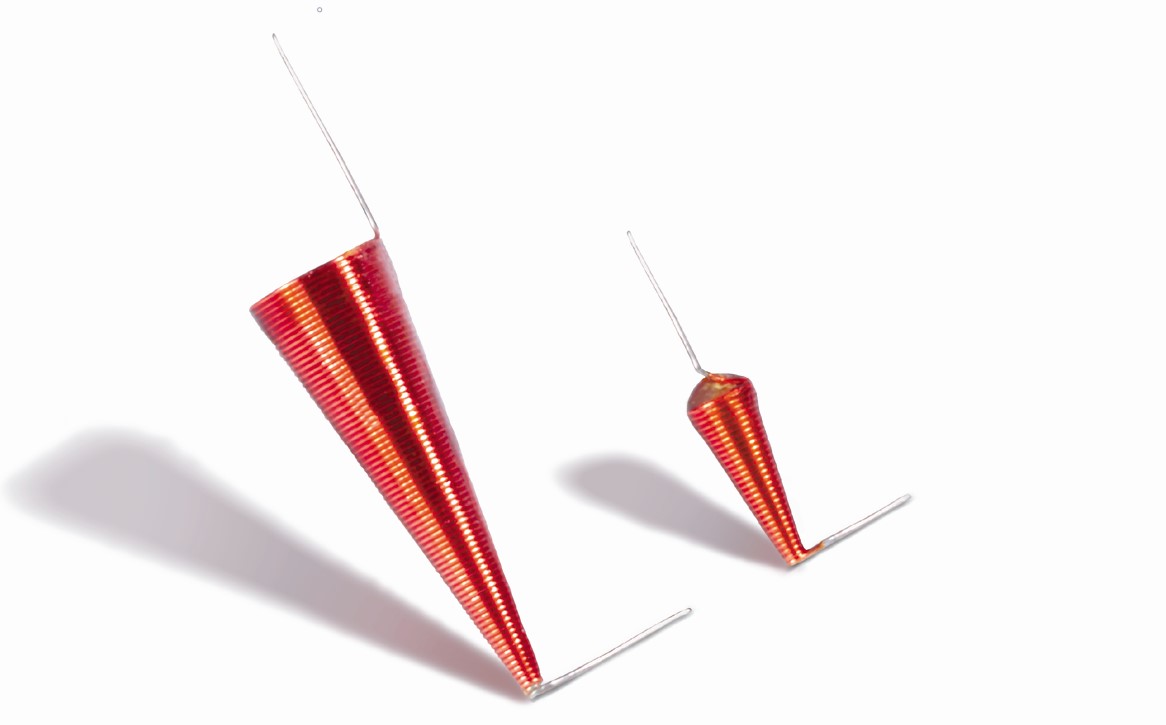
Coilcraft offers two versions of conical inductors, the BCL and the BCR. The BCL comes with “flying leads” designed for hand soldering to the PC board and allows for varying the angle at which it is mounted. The BCR is secured in a mounting bracket that allows reflow soldering to the PC board, but does not provide for varying the angle.

Mounting the BCL

The BCL can be mounted flat to the board or can be positioned so that it is at an angle to the board. Soldering the part flat may reduce high frequency response on some substrates. If the board substrate is a high frequency laminate there may be no degradation in performance when the inductor is mounted flat.

To ensure the best performance, the part should be mounted at an angle with the small end closest to the board. We have found that an angle of 40° to 60° yields the best results, with there being only a slight improvement above 40°. Experimentation in your particular application on your PC board is the only way to determine the best mounting angle or if an angle is necessary at all.
 
Doc556-BCL.jpgDoc556-BCR-531JLB-high-res-(1).jpg
The BCL, pictured on the left, comes with “flying leads” designed for hand soldering to the PC board. The BCR , pictured on the right, is secured in a mounting bracket that allows reflow soldering to the PC board

You can use a small amount of glue help hold the part at the desired angle prior to soldering. Make sure that the glue is designed for high frequency applications. Use just enough glue to achieve what you are trying to do. Too much glue can have a negative effect on the performance of the coil. The main objective is to keep stray capacitance to a minimum. A conductive epoxy may be used instead of the solder to help minimize stray capacitance.

Cut the lead from the small end of the coil to a length that allows positioning to the board and provides enough lead for a good solder connection. Point tip solder the lead to the PC board. Use the soldered lead as a pivot point and raise the large end of the part to the desired angle. Fashion the lead from large end so it acts as a stand and holds the part at the selected angle. Then solder that lead to the board.

Mounting the BCR

The BCR is designed to be reflow soldered to the PC board. The inductor is mounted to the bracket at a fixed angle (approximately 10°). This angle provides lowest profile possible and acceptable performance for most applications. Coilcraft recommends requesting samples before ordering parts for a production run. The mounting bracket does, to some extent, mitigate the negative effect that the PC board substrate may have on the part. A recommended land pattern for each size is provided on the data sheet.
Doc 556

Questions or Concerns?

Ask View FAQs


General Applications

Handling and Processing

RF Inductors

Power Conversion

EMI/RFI Filtering

Special Applications