站点设定

仓库
语言设定
货币设定
资源
视频库
Cx Family Common Mode Chokes
0402CT Low Profile Chip Inductors
XAL7050 High-inductance Shielded Power Inductors
XGL4020 Ultra-low DCR Power Inductors

A Simple Guide to Understanding and Selecting Coilcraft Push-Pull Transformers

What is a Push-Pull transformer?

Push-pull transformers are forward-mode transformers with center-tapped primary and secondary windings that are used in 2-switch, open-loop, fixed-duty cycle circuits and in closed-loop, wide input voltage range, push-pull converter circuits. They provide circuit isolation and voltage transformation, step-up or step-down, if needed. They are used over a wide power range from 1/4 Watt to hundreds of Watts. This article discusses advantages, basic operation, applications, and selection of push-pull transformers.

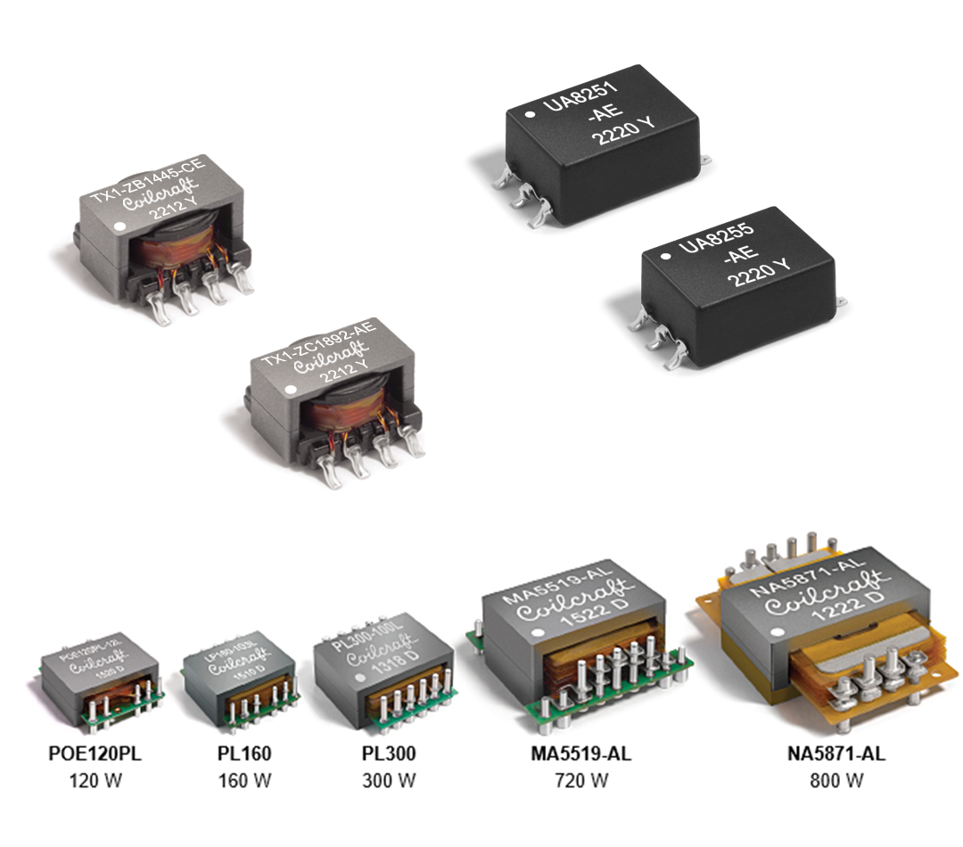
pushpulltransformers.png 
Coilcraft Off-the-Shelf Push-Pull Transformers
 

Advantages

A major advantage of push-pull converters is that the 2-switch operation shares the load across two power switches such that each switch only handles every other power pulse. This means that the transformer is effectively only operating at half the switching frequency.

As with the single-ended forward topology, the voltage stress on the FETs in the push-pull topology is two times the input voltage. A typical rule of thumb is to limit the primary current ripple to 10-30% of the average primary current to limit stresses on the switches, generally holding EMI to within reasonable limits.

In addition, push-pull transformers have inherently lower EMI than flyback transformers because they are designed to have less interwinding capacitance than flybacks, which are designed for low leakage inductance and therefore have inherently higher capacitance. Lower EMI also means smaller components can be used if an LC filter is used to reduce the output ripple.

Operations and Waveforms

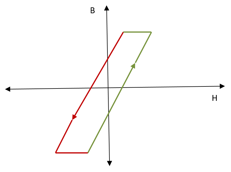
Push-pull-b-h-curve.png
Push-pull B-H Curve Two-Quadrant Operation
Figure 1

Push-pull transformers used in open-loop operation drive the center-tapped primary at 50% duty cycle with two-quadrant (bipolar) excursions of the BH-loop, the B and H excursions reversing polarity and crossing zero each alternate half-cycle (Figure 1).

Two-quadrant operation means the transformer core flux that builds up in one phase is ideally cancelled by that of the other phase, preventing permanent flux build up. Winding assymmetry can create imperfect matching of flux in each quadrant which can lead to flux build up. In such cases, current-mode control may be used to reset the core.

The relatively low ripple current and two-quadrant operation of push-pull (versus, for example, flyback) results in high efficiency and may allow the use of a smaller transformer. The cancelling of common mode flux also creates lower EMI and better transient immunity. Figure 2 shows typical push-pull topology current paths and waveforms.

Push-pull-current-paths-waveforms-(1).png
Push-pull Current Paths Waveforms. Source: Texas Instruments http://www.ti.com/lit/an/slyt790a/slyt790a.pdf
Figure 2
 

The major design considerations of a push-pull transformer are turns ratio and power handling. Turns ratio directly determines the output voltage: Vout = Vin x D x 2 x Ns/Np (eq. 1).

As with forward mode topologies, higher magnetizing inductance helps improve efficiency, but inductance is not a major design consideration and tight tolerance is not required. Figure 3 shows a 1:4 turns ratio push-pull transformer used in an isolated push-pull power supply circuit to convert 5V to isolated +/- 15V.
 

SN6501-(2).png
Isolated Low-EMI Push-Pull Converter Power Supply Circuit
Source:  Texas Instruments  http://www.ti.com/lit/an/slyt790a/slyt790a.pdf
Figure 3
 

Applications

The push-pull topology is an excellent choice for:

  • Ultra-low noise isolated DC-DC converters
  • Automotive (for smaller, lower-weight components) and low EMI
  • Inverting and non-inverting output power supplies
  • Low- or high-power industrial applications
  • Low-noise data communications
  • Multiple outputs / Distributed power
  • Higher-frequency power supplies using compact transformers

Selecting Coilcraft Push-pull Transformers

Selecting the appropriate off-the-shelf Coilcraft push-pull transformer starts with determining the output power and turns ratio requirements of the application. Consult the datasheet for your selected push-pull driver IC to determine the appropriate turns ratio. An approximation of the output power requirement of the transformer is Vout x Iout, adding an extra few percent to account for imperfect efficiency.

Selection Made Simple

Coilcraft is pleased to present our powerful online Power Converter Transformer Parametric Search tool.

To view a list of all Coilcraft push-pull transformers:
1. Select Power Converter Transformers
2. Select the Topology filter from the Narrow results menu
3. Click the Push-pull checkbox in the Topology filter
4. Click Apply.

Applying the appropriate Narrow results selection filters helps you quickly find a push-pull transformer meeting your application requirements.

1. Select the Output Power filter, and either enter a range or select from the pull-down list.
2. Select or enter the appropriate turns ratio(s) and any other factors considered important to your selection (e.g. Vin, Vout, isolation voltage, size).

Results can also be sorted by any parameter to quickly find the most appropriate solution for your application. For example: Are you looking for a push-pull transformer designed for use with the Texas Instruments SN6507 IC? Select the Designed for filter and select Texas Instruments. Coilcraft TX1 series includes several turns ratio and output power options.

The push-pull topology affords proven advantages in many power and communications applications, including automotive and industrial automation. Coilcraft's powerful MagProTM   parametric search utility is a time-saving tool for simplifying the selection of optimal off-the-shelf push-pull transformers.


References

Push-pull converter simplifies isolated power supply design in HEV/EV systems, Texas Instruments, Analog Design Journal 1Q 2020, Anant Kamath, slyt790a, http://www.ti.com/lit/an/slyt790a/slyt790a.pdf

LM5030 Application: DC-DC Converter Utilizing the Push-Pull Topology, Literature Number: SNVA553, Texas Instruments (employs Coilcraft A9784-B)  http://www.ti.com/lit/pdf/snva553 

How to Design an Isolated, High Frequency, Push-Pull DC/DC Converter by Dawson Huang, Analog Devices,  https://www.analog.com/en/technical-articles/high-frequency-push-pull-dc-dc-converter.html

LT3999 datasheet for low noise, 1A, 1 MHz, push-pull DC-DC driver  https://www.analog.com/en/products/lt3999.html#

Fundamentals of Power Supply Design, Robert A. Mammano, 2017