Ferrite beads, or ferrite chokes, are used as low pass filters to eliminate high frequency noise while allowing low frequency signals or DC current to pass through a circuit. The noise may come from any number of sources including high-frequency switching noise from a power-supply circuit or RF noise in an RF signal-isolation circuit that must be minimized to ensure both signal integrity and antenna efficiency.
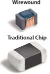
Ferrite beads, whether chip or wirewound, are used to filter electromagnetic interference (EMI). You may be surprised to discover that wirewound ferrite beads provide a high magnitude of attenuation over a wide frequency range, whereas traditional thick-film chip ferrite beads have limited options for both attenuation and frequency range.
In addition to offering better attenuation and frequency performance than their chip counterparts, wirewound ferrite beads also provide lower DC resistance (DCR) and higher current ratings without core saturation, resulting in the highest possible performance in the smallest size.
Coilcraft wirewound ferrite beads come in standard package sizes from 0201 (0603) to 1812 (4532), all providing extremely low DCR while maintaining high filtering impedance over the broadband frequency range. These features enhance the performance of the choke circuit while potentially reducing board space by replacing a larger chip ferrite bead with an equivalent, or higher-performing wirewound ferrite bead.
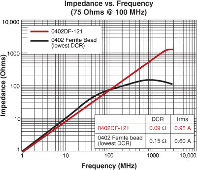
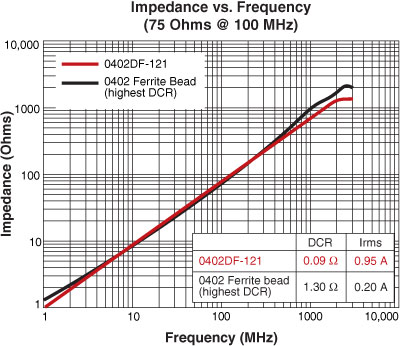
Figure 1 and Figure 2 demonstrate how Coilcraft wirewound ferrite beads provide superior broadband performance compared to both low- and high-DCR chip ferrite beads. Figure 1 compares the Coilcraft 0402DF-121 wirewound ferrite bead to the lowest-DCR 0402-sized chip ferrite bead. The 0402DF offers higher impedance across the frequency range, providing a greater measure of filtering from 100 MHz and above. Compared to typical high-DCR chip ferrite beads, the Coilcraft wirewound ferrite bead maintains the same high frequency attenuation while providing higher current ratings and 40 percent better DCR.
Series | Size | Max Height | Impedance Range (Ohms) |
---|---|---|---|
0201AF | 0201 (0603) | 0.18 mm | 19.89 - 118.6 @ 100 MHz 159.9 - 1,089 @ 900 MHz |
026011F | 0201 (0603) | 0.25 mm | 91.52 - 320.5 @ 100 MHz 747.2 - 3,435 @ 900 MHz |
0402DF | 0402 (1005) | 0.66 mm | 11.98 - 5,270 @ 100 MHz 93.76 - 7,628 @ 900 MHz |
0402AF | 0402 (1005) | 0.66 mm | 11.23 - 331.3 @ 100 MHz 82.23 - 3,593 @ 900 MHz |
0603AF | 0603 (1608) | 0.91 mm | 8.83 - 3,807.7 @ 100 MHz 48.14 - 6,332 @ 900 MHz |
0603LS | 0603 (1608) | 1.12 mm | 28.21 - 5,760 @ 100 MHz 27.89 - 3,815 @ 900 MHz |
0805AF | 0805 (2012) | 1.52 mm | 65.61 - 7,069 @ 100 MHz 26.14 - 2,451 @ 900 MHz |
0805LS | 0805 (2012) | 1.60 mm | 48.54 - 7,765 @ 100 MHz 28.82 - 2,265 @ 900 MHz |
1008AF | 1008 (2520) | 1.91 mm | 6.09 - 66.51 @ 1 MHz 59.29 - 721.8 @ 10 MHz |
1008LS | 1008 (2520) | 2.03 mm | 6.56 - 682.9 @ 1 MHz 63.95 - 7,511 @ 10 MHz |
1812LS | 1812 (4532) | 3.43 mm | 77.85 - 7,167 @ 1 MHz 770.7 - 191,219 @ 10 MHz |