サイトの設定

倉庫
言語の設定
通貨の設定
製品
リソース
ビデオライブラリ
Cx Family Common Mode Chokes
0402CT Low Profile Chip Inductors
XAL7050 High-inductance Shielded Power Inductors
XGL4020 Ultra-low DCR Power Inductors

Passive LC Filter Design and Analysis

Using measurement-based models for design and analysis

Passive electronic LC filters are used to block noise from circuits and systems. Ideal filters pass the required signal frequencies with no insertion loss or distortion, and completely block all signals in the stop-band. Real filters have DC and AC resistances that contribute to insertion loss, requiring careful component selection.

Selecting the exact values of the components required for a particular application may appear to be a daunting task for beginners. Filter categories include lowpass, highpass, bandpass, bandstop, all-pass, and multiplexers. The simplest to design and implement are the lowpass and highpass types.

A number of possible filter alignments exist, including Butterworth, Bessel, Chebyshev, and elliptic. Selection of the filter alignment involves trade-offs in flatness of the frequency behavior versus sharpness of the cut-off. The very simplest LC filter consists of an inductor and a capacitor. Higher-order filters use more components to give a sharper, more defined roll-off for better attenuation of unwanted noise. See Appendix A for details.

The good news is that modern circuit synthesis and analysis programs can quickly perform the otherwise tedious and time-consuming calculations. Filter synthesis programs generate the required inductance (L) and capacitance (C) values. Analysis programs simulate the results after the user enters the appropriate values. Once the initial ideal values have been calculated, practical solutions are created using off-the-shelf components.

Modeling Filter Behavior

Ideally, one could simply define the band of frequencies to be passed, those to be blocked, and a program would generate standard component values resulting in the actual on-board performance.

Free programs for generating basic filter designs are available on the internet, such as Design LC Filters (V 3.0) at http://www.wa4dsy.net/filter/filterdesign.html. Programs like this synthesize a filter design using ideal element values as a starting point. If the design results are not standard values, some compromises in performance may be necessary. Substitute standard part values and run a circuit simulation to determine effects on the filter performance.

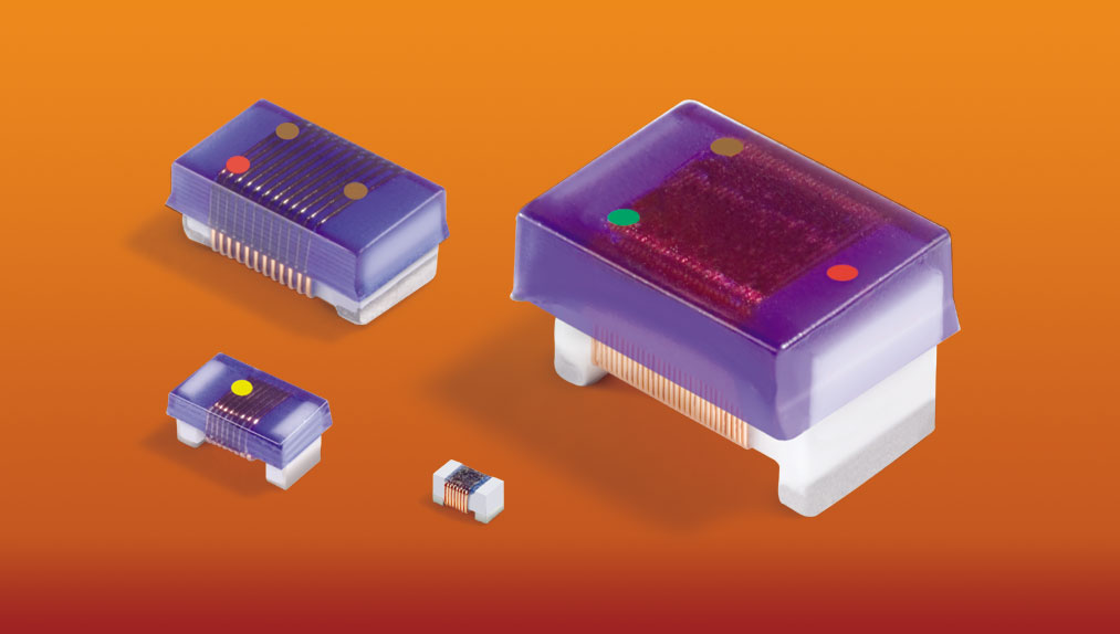
Doc1021-ChipInductor.jpg

Coilcraft offers a wide variety of tight-tolerance ceramic chip inductors, SPICE models, and design support.

For lower-frequency filter designs, ideal component models may be sufficient for analysis. However, the effects of circuit parasitics of inductors, capacitors, and circuit board traces may require selection of slightly different component values to tune the performance of higher-frequency filters. In this case, for better prediction of the real filter, accurate inductor models and circuit board trace and pad models should be involved. For many designs, accurate inductance models based on actual component measurements are necessary, but ideal capacitors can be used for the simulation. Simulations of filters approaching the Gigahertz range may require non-ideal capacitor models as well.

Coilcraft offers free, accurate, measurement-based models of many off-the-shelf inductors, including detailed instructions for implementing them in popular simulation programs, at this link: http://www.coilcraft.com/models.cfm. These inductor models help get your filter design closer to real performance than simpler, ideal inductor models.

Finally, a prototype board should be assembled, tested, and tweaked if necessary. Once the design appears to be acceptable, analysis of the effects of component tolerances can be performed.

Demonstrated Low Pass and High Pass Solutions

To simplify LC filter design, Coilcraft has created LC filter reference designs, including 3rd order Butterworth lowpass and high-pass, and 7th order elliptic filters. These designs demonstrate the high performance that can be achieved using Coilcraft inductors and standard capacitors.

References

Rhea, Randall W., HF Filter Design and Computer Simulation (Noble Publishing Corporation, 1994)

Vizmuller, Peter, RF Design Guide (Artech House, Inc., 1995)

Williams, Arthur B., Electronic Filter Design Handbook (McGraw-Hill, 1995)

Appendix A – Filter Alignments and Properties

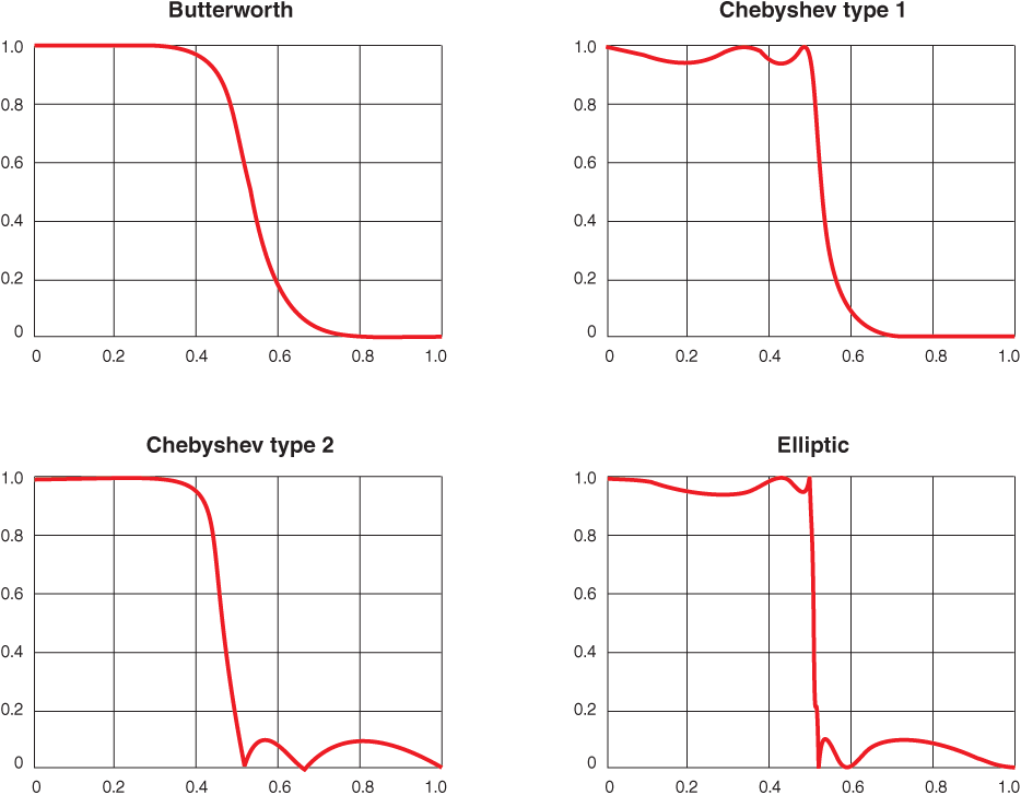
Butterworth – Maximally flat (more linear) pass-band response, slower roll-off, flat stop-band response. Requires a higher order to achieve a specific stop-band spec. vs. Chebyshev and Elliptic.

Chebyshev (Type 1) – More pass-band ripple, sharper roll-off, flat stop-band response

Chebyshev (Type 2) – Flat pass-band response (requires more components), sharper roll-off, more stop-band ripple

Elliptic (Cauer) – Sharpest roll-off, more pass-band ripple and stop-band ripple. Equiripple elliptic filters are maximally insensitive to component variation.

Bessel – Maximally flat group delay (maximally linear phase response) that preserves the wave shape of signals in the pass-band.

Increasing the number of filter elements increases the performance of the filter.

The following curves are the results of 5th order, low pass filters.

Doc1021-Curves.gif

Source:http://en.wikipedia.org/wiki/Electronic_filter

Doc 1021

Questions or Concerns?

Ask View FAQs


General Applications

Handling and Processing

RF Inductors

Power Conversion

EMI/RFI Filtering

Special Applications