サイトの設定

倉庫
言語の設定
通貨の設定
製品
リソース
ビデオライブラリ
Cx Family Common Mode Chokes
0402CT Low Profile Chip Inductors
XAL7050 High-inductance Shielded Power Inductors
XGL4020 Ultra-low DCR Power Inductors

Inductors as RF Chokes

Solving RF Isolation Issues with RF Inductors

Introduction

Many consumer products communicate with each other over broadband networks. From television to fiber transmission networks, the bandwidth of data communication is increasing, and the integrity of RF signals has become a major design concern. This paper provides examples of how different inductors can be used for RF isolation in a range of circuits from relatively narrow band applications like portable devices up to broadband networks for data distribution. The different types of inductors used in these applications are identified and discussed.

Why an Inductor?

By its nature, an inductor is a low pass filter (XL = ωL). At high frequency the inductor becomes a high impedance element that can be used for RF isolation. High frequency cannot pass through the inductor, but dc current and very low frequency signals are allowed to pass. Without this type of isolation, antenna efficiency can diminish, signal loss can occur and RF noise can interfere with other parts of the circuit., shown below

The peak of inductor impedance occurs at the natural self resonant frequency (shown below).

f = 12π√LC

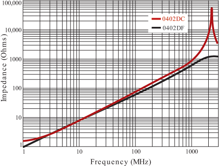
The magnitude of the peak impedance is related to the quality factor (Q-factor) of the inductor. Low loss inductors with high Q (i.e. Coilcraft 0402DC) have a very high peak impedance, while a lossy inductor (i.e. Coilcraft 0402DF), has a lower peak impedance (See Figure 1).

By changing the way a coil is wound or the materials used in the construction, multiple resonances can be aligned to provide high impedance over a wide bandwidth. This is what occurs in Coilcraft Conical Inductors.

Applications

High Q ceramic or air inductors, like the 0402DC, shown in Figure 1, can be used when a narrow frequency band needs to be blocked, like small-signal, high-frequency communication lines on handsets.

Doc945-Figure1.gif

Figure 1. Coilcraft 0402DC & 0402 120 nH Impedance

On the other hand, for an audio line inside a handset where it is important to limit low frequency losses, using a ferrite part like the 0402DF is ideal. While the peak impedance is lower, the dc resistance is only a third or less than that of the ceramic core counterpart.

One application driving demand for this type of product is the integration of the antenna into the case of the phone. In the past an external antenna would be used to ensure the antenna remained isolated from the rest of the phone components. Recently the integrated antenna is often placed near a speaker, microphone or keyboard, which needs to be isolated from the antenna frequencies to prevent coupling to the antenna.

In broadband applications, most inductors do not cover enough bandwidth. By putting three or four inductors in series, a broader band can be covered, but dc loss increases. Since size is not as critical in many broadband applications, there is often room to keep the broadband portion of the circuit isolated with ground planes, shields, etc. There are also instances where DC current is injected onto RF lines. For these applications, RF inductors provide the isolation function, blocking the RF signal from the DC bias source.

Doc945-Figure2.gif

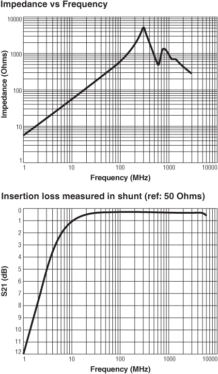
Figure 2. 4310LC Characteristics

For an example requiring RF isolation, a television antenna may need up to 500 mA injected onto the RF line, while blocking frequencies from 20 MHz to 2 GHz. Consider the isolation that can be achieved with a Coilcraft 4310LC wideband inductor.

As shown, the impedance of the 4310LC remains greater than 100 Ohms from 20 MHz to above 3 GHz. The insertion loss measurement shown is for the coil connected in shunt from a transmission line to ground. This curve illustrates how frequencies below 10 MHz are lost to the ground plane (pass through the component) and that frequencies between 10 MHz and 6 GHz are rejected by the coil and pass along the transmission line.

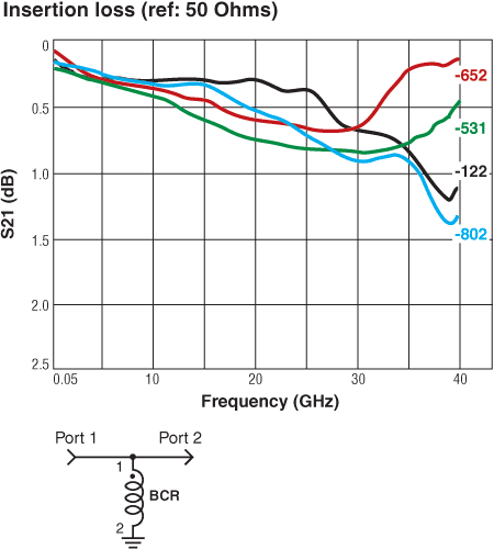
Another application requiring RF isolation is the biasing of a pin diode for use in fiber networks. Here, a 200 mA dc injection is needed on an RF line that carries frequencies from 100 MHz to 30 GHz. To meet this requirement, any Coilcraft BCR Conical Inductor can be used.

Doc945-Figure3.gif

Figure 3. Broadband Conical Inductors

Figure 3 shows that the insertion loss using BCR inductors from 50 MHz to 35 GHz is less than 1.0 dB when the component is measured in shunt from a transmission line to ground.

The critical determination when choosing RF chokes is the frequency range that needs to be blocked. Other key parameters are dc resistance, current requirements, size and cost. From that, online tools like the Highest Impedance Finder or RF Inductor Comparison tool from Coilcraft can help identify the right RF choke for narrow band applications. Tools are still in development for larger bandwidths.
 

Summary

It is critical for designers to maintain RF integrity without sacrificing overall circuit size or cost. In handset applications, the integration of the antenna to the case of the phone increases the demand for RF isolation inductors on transmission lines. The need to provide bias on RF lines requires “bias chokes,” which perform the same function as an RF isolation choke.

For any of these applications, an inductor is the key to success. Start with identifying the frequency range of the application, and then determine what the other parameters need to be. If one coil is not able to provide the solution, a network of inductors may be required. That will be the subject of another application note.

Doc 945

Questions or Concerns?

Ask View FAQs


General Applications

Handling and Processing

RF Inductors

Power Conversion

EMI/RFI Filtering

Special Applications