Site Settings

Warehouses
Language settings
Currency settings
Resources
Video Library
Cx Family Common Mode Chokes
0402CT Low Profile Chip Inductors
XAL7050 High-inductance Shielded Power Inductors
XGL4020 Ultra-low DCR Power Inductors

Testing Inductors at Application Frequencies

Why testing at actual circuit frequency is critical to ensuring desired inductor performance

Introduction

The accurate measurement of an inductor has always been more difficult than the measurement of other passive components. The primary difficulty with coil measurements lies in the fact that coil inductance and its efficiency are quite frequency dependent. Similarly, coil parasitics (distributed capacitance and core/copper resistive losses) vary dramatically with frequency. The measurement of a coil at the application frequency, so-called “use frequency testing,” is more representative of the basic value of the component in circuit than testing at traditional standard frequencies.

Often, the value of a measurement frequency is specified for measurement convenience alone. If the measurement frequency is not the circuit (or “use”) frequency, the result of testing generally will not yield the same inductance value or display the same efficiency as seen by the intended circuit. Because equipment and methods now allow more flexibility in test frequency selection, inductors should be tested at the actual frequency of use, particularly if tight tolerances are required.

Inductor parameters

The primary electrical parameters of an RF inductor are inductance, Q (efficiency), the direct current resistance (DCR) and self-resonant frequency (SRF). All primary electrical parameters are design controlled, although not independently. The measured inductance and Q are often highly dependent on the test instrumentation and the frequency at which the test is performed.

Q is the ratio of imaginary to real impedance, and is related to the efficiency of an inductor as the ratio of stored energy to dissipated energy. Q describes the energy storage capability of an inductor as directly proportional to the frequency at which it is being measured and inversely proportional to the resistive (copper and core) losses the component displays at the same frequency.

DCR is the resistance of the wire used in the inductor as seen by a direct, non-varying current. DCR gives us an idea of the insertion loss the inductor will add to the circuit by its simple insertion into the circuit. DCR also indicates how much energy the inductor will waste in simply heating up.

SRF is the frequency above which the component no longer functions as an inductor. The SRF is determined by the parallel combination of the (low frequency) inductance and the effective capacitance accumulated between the turns of the coil.

Test equipment

The appropriate selection of a method of test largely determines the accuracy of a measurement. Instrumentation and test methods vary for individual electrical parameters, and every instrument has further limitations in terms of range, frequency, and error. Parasitics and their effects associated with test fixturing is a significant consideration in a measurement. In all cases, the instrument, fixturing, frequency, and current (if applicable) must be specified in order to have a repeatable and reliable test.

An impedance analyzer is generally used for the inductance and Q measurements of an inductive component. The SRF can be measured by noting the zero crossing of the phase on a network analyzer. The DCR is usually measured on a low ohmmeter.

The selection of instrumentation also influences measured values. The influence of an instrument is the result of the various measurement methods and frequencies employed by each piece of equipment.

Part of the discrepancy can be attributed to the different instruments, but the majority is due to the different frequencies. In general, the proper instrument to specify is one that is accurate and repeatable at the frequency required.

The latest-available impedance analyzers for measuring L and Q of RF inductors have accurate phase calibration standards and measure as high as 3 GHz to facilitate testing at application frequencies.

Traditional method of specifying and testing inductors

Before the advent of impedance analyzers, Q meters were used to measure L and Q. These meters were cumbersome to use and had low accuracy. They also required setup “standards” which were similar to correlation pieces. Correlation pieces are similar to standards in that they are identified both by the vendor and user as having a particular value. Correlation pieces are deemed to be the standard for a particular inductor and are used to set up each instrument every time a test is performed. Correlation is still the most accurate method, resulting in very little error, excellent repeatability and is applicable at any frequency. However, the method of correlation has significant logistical disadvantages: the establishment and accountability of specific correlation pieces between the manufacturer and the customer.

The other electrical parameters, SRF and DCR are generally specified along with L and Q but there is rarely any reference to the test method used. The lack of a specific method of testing SRF and DCR reflects the fact that the inductance is the dominant parameter and one that requires the most diligent control.

Application frequency testing

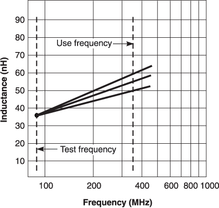
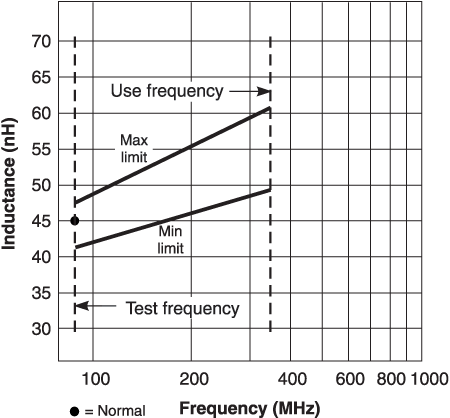
The basic complication with the traditional testing method is that the coils are tested at one frequency and used at another frequency. The graphs in Figures 1 and 2 show the fundamental problem with the traditional testing method.

Inductance vs frequency

Figure 1 shows a log sweep of inductance vs. frequency for three different inductors. When these parts are tested at a standard frequency, they appear to be identical in terms of inductance. At the actual circuit frequency, these coils are quite different. These three coils can represent three different designs or three different coils of the same design. If the use frequency is the point where all three converge, then these coils are effectively the same. If the circuit frequency is significantly different from the test frequency, then the inductance at the use frequency cannot generally be implied from the test frequency.

Even if these coils had not deviated from each other, there is still a change in inductance. The consequence of an inductance shift with frequency is generally observed when a design requires a specific inductance and the particular coil does not perform as expected. The shift is generally attributed to fixturing differences and circuit parasitics and the specified value is compensated accordingly.

Figure 2 shows another consequence of testing at a frequency other than the application frequency. It displays an inductance vs. frequency sweep for a particular coil. The normal inductance is indicated at both frequencies along with their tolerances. If this coil had been specified as a 5% inductor at the test frequency, it would have resulted in a 10% tolerance at the application frequency. These limits could have compressed over frequency or spread even more, depending on the coil. The fact that the limits are not constant with respect to each other results in a loss of tolerance control over frequency.
 
Doc119-Figure-1.gif
Figure 1. Inductance change with frequency for three different inductors
 
Doc119-Figure-2.gif
Figure 2. Tolerance change with frequency for an inductor

In all cases where the inductance changes with frequency, testing at the application frequency results in better specification control. Testing at the application frequency, particularly with correlation, can be an extremely effective and superior method of determining the application suitability of a coil.

Specifying Inductor Tests at Application Frequencies

The procedure to specify and the electrical test for an inductor at use frequencies is as follows:

Inductance
  1. Specify the nominal inductance.
  2. Specify the test instrument, fixture, calibration and fixture compensation methods, and frequency.
  3. Specify the inductance tolerances.
    1. Determine the allowable tolerance as a percentage using 6 sigma or other appropriate methods.
    2. Evaluate the instrument error for the nominal impedance at the test frequency. Subtract this error percentage from the allowable tolerance found in step 3a.
    3. Establish the instrument and fixture repeatability. Subtract this error percentage from the result of step 3b. This result is the tolerance to specify. The manufacturer should test to the specified tolerance without correlation as all errors have been accounted for.
Q
  1. Specify the absolute minimum Q (allowable minimum). Determine the allowable minimum using 6 sigma or other appropriate methods. The customer should test to this tolerance.
  2. Specify the test instrument, fixture, calibration and fixture compensation methods, and frequency.
  3. Specify the Q minimum for manufacture.
    1. Evaluate the instrument error for the nominal impedance at the test frequency. Adjust the allowable minimum found in step 1 (i.e., increase the minimum Q by an amount equal to the instrument error).
    2. Establish the instrument and fixture repeatability. Adjust the new allowable minimum found in step 3a (i.e., increase the minimum Q by an amount equal to the test repeatability). This result is the tolerance to specify. The manufacturer should test to the specified tolerance without correlation because all errors have been incorporated into the final adjustment of the Q specification.
DCR
  1. Specify the absolute maximum DCR (allowable maximum). Determine the allowable maximum using 6 sigma or other appropriate methods.
  2. Specify the test instrument and fixture.
  3. Specify the DCR maximum for manufacture.
    1. Evaluate the instrument error for the nominal resistance. Adjust the allowable maximum found in step 1 (i.e., decrease the maximum DCR by an amount equal to the instrument error).
    2. Establish the instrument and fixture repeatability. Adjust the new allowable maximum found in step 3a (i.e., decrease the maximum DCR by an amount equal to the test repeatability). This result is the tolerance to specify. The manufacturer should test to the specified tolerance without correlation because all errors have been incorporated into the final adjustment of the DCR specification.

SRF

SRF is typically not a specification. A typical reference value or typical minimum value may be published. Q and SRF will track the measured inductance value. Therefore, only inductance typically needs to be tested for qualification.

Specifications With Correlation

The use of correlation in conjunction with use frequency testing can eliminate errors due to different fixture and environmental factors and allow the specifications to be tightened. It may not be needed for higher inductance values. Correlation can be used with any of the inductor parameters but is most often applied to inductance and Q.

Conclusion

Coil inductance and Q are frequency dependent and testing methods have further influence on these parameters. Specifying and testing at the actual circuit frequency is an appropriate method of controlling inductor parameters. Use frequency testing ensures that components are consistent with their intended application.

The primary inductor parameters are interrelated design functions of the coil. The inductor specification should take into account the component variations and measurement system errors.
Doc 119

Questions or Concerns?

Ask View FAQs


General Applications

Handling and Processing

RF Inductors

Power Conversion

EMI/RFI Filtering

Special Applications