Site Settings

Warehouses
Language settings
Currency settings
Resources
Video Library
Cx Family Common Mode Chokes
0402CT Low Profile Chip Inductors
XAL7050 High-inductance Shielded Power Inductors
XGL4020 Ultra-low DCR Power Inductors

Selecting the Best Inductor for Your DC-DC Converter

Understanding the Data Sheet

Abstract

Proper inductor selection requires a good understanding of inductor performance and of how desired in-circuit performance relates to the information available in supplier data sheets. This article walks both the experienced power conversion specialist and nonspecialist through the inductor catalog and the important specifications.

Introduction

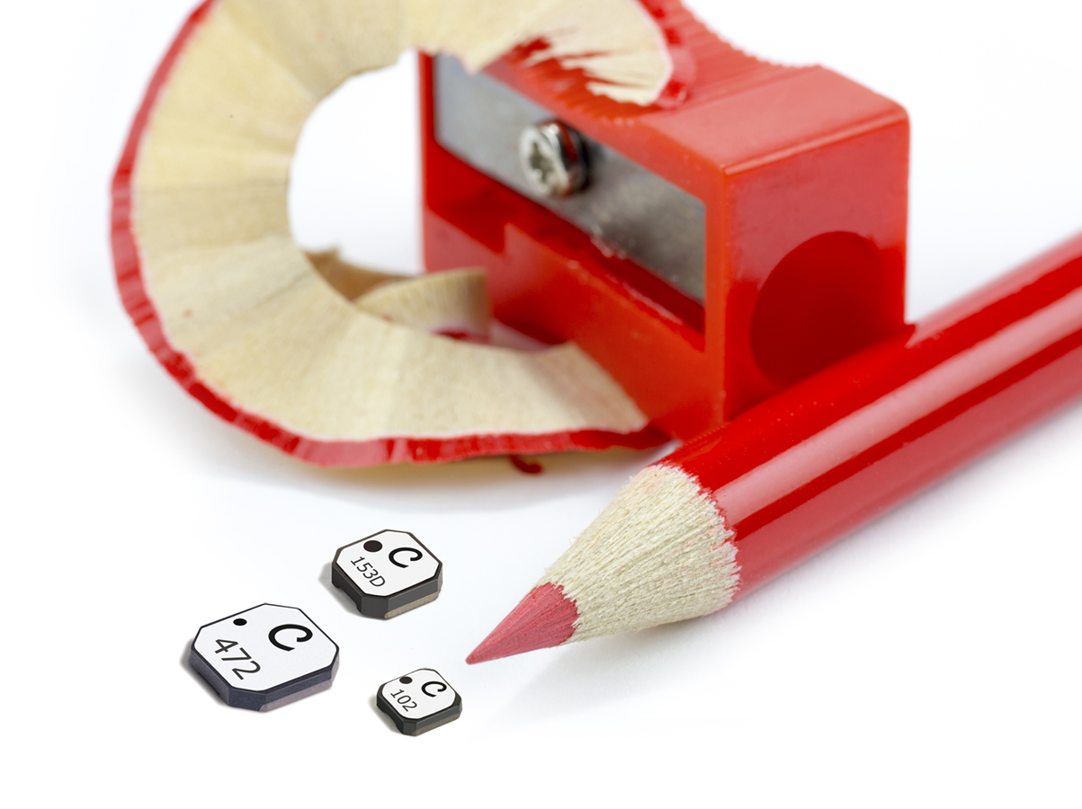
The use of dc-dc converters is increasing. As electronic systems become more miniaturized, mobile, complicated, and popular, the power requirements become more varied. Available battery voltages, required operating voltages, size, and shape requirements are ever changing, leaving equipment designers constantly in need of new power conversion solutions. As product requirements constantly drive performance improvement and size reduction, optimization is crucial. A “one size fits all” approach to power conversion does not fit all applications. For example, low profile components as shown in Figure 1 are much in demand. 

Doc469-Fig1.jpg

Figure 1. Thin Inductor Shapes Allow Low Profile Converter Design

Not only is the market for purchased converters growing, but also many circuit designers now design their own dc-dc conversion circuits instead of relying on power supply specialist companies. This increases the number of circuit designers involved in selecting components. Basic dc-dc conversion circuitry is fairly mature technology and continues to evolve rather slowly. Because of this it has become quite practical and useful for authors to create “cookbook” design aids by which equipment designers can create their own converter design. Software is also readily available to facilitate these designs1.

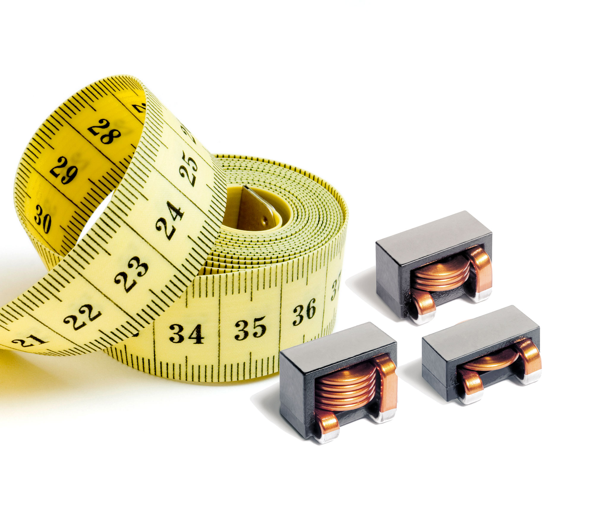
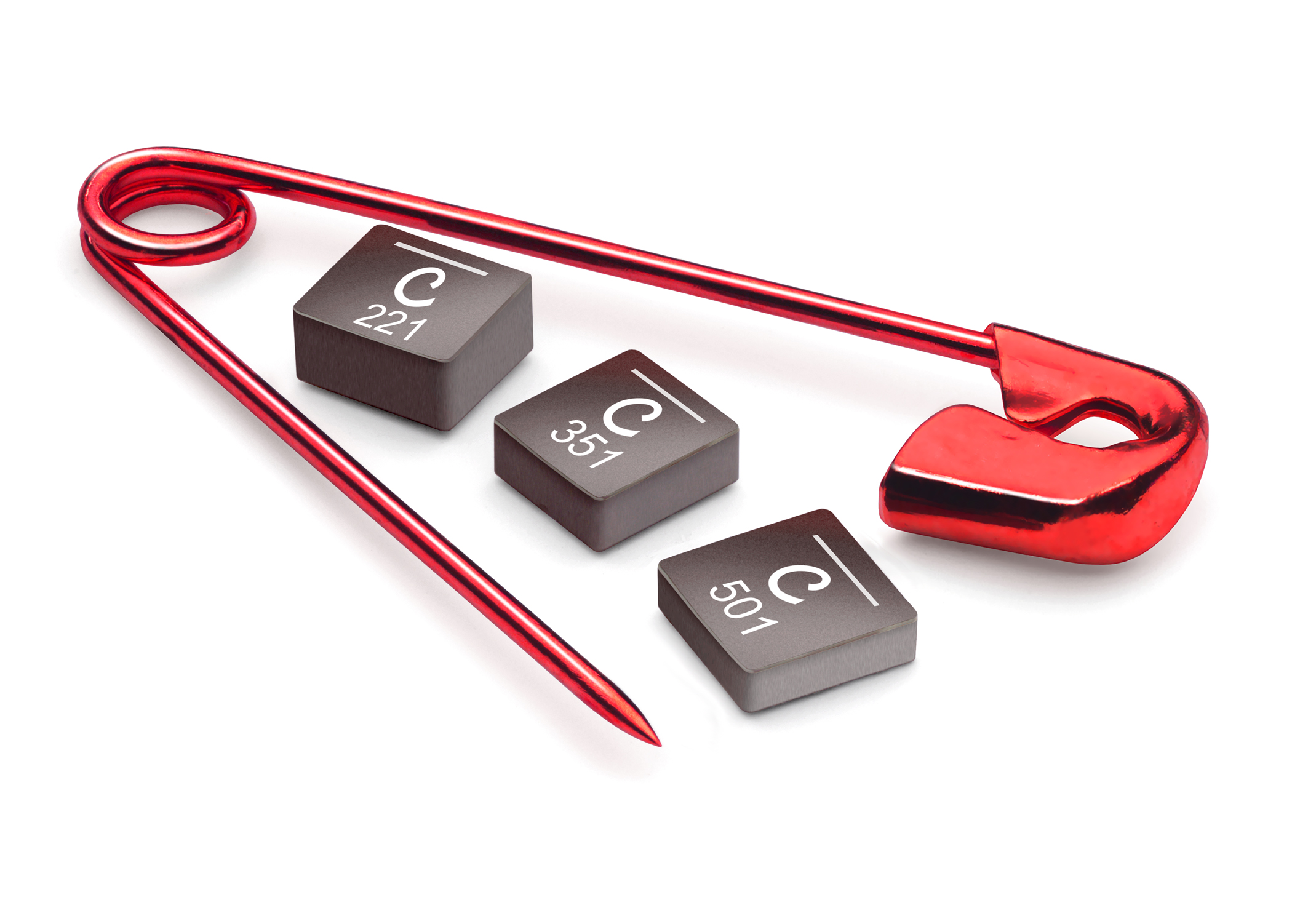
After deciding on a circuit topology, one of the key design tasks is component selection. Many circuit design programs produce a list of the required component values. The task for the designer then is to get from knowing the desired inductance value to selecting an available component to do the job. Inductors that can be used in dc-dc converters come in a wide variety of shapes and sizes. Figures 2 and 3 show just two of the possible inductor shapes. In order to compare types and choose the optimal part for the application, a designer must rely on correctly understanding published specifications.

Doc469-Fig2.jpg
Figure 2. E-Core Inductor with Flat Wire

Doc469-Fig3.jpgFigure 3. Molded inductors are mechanically rugged and magnetically shielded for use in high density circuits
DC-DC Converter Requirements

Simply stated, the function of a dc-dc converter is to provide a stable dc output voltage from a given input voltage. The converter is typically required to regulate the dc output voltage given a range of load currents drawn and/ or range of input voltage applied. Ideally the dc output is to be “clean”, that is with ripple current or voltage held below a specified level. Furthermore, the load power is to be delivered from the source with some specified level of efficiency. Power inductor selection is an important step to achieving these goals.

Power Inductor Parameters

Inductor performance can be described by a relatively few numbers. Table 1 shows a typical data sheet excerpt for a surface mount power inductor intended for dc-dc converters.

Table 1. Typical Inductor Catalog Excerpt2

Part number L ±20%a
(µH)
DCR max
(mOhms)
SRF typ
(MHz)
Isatb
(A)
Irmsc
(A)
XAL4020-102 1.0 14.6 79 8.7 9.6
  1. Inductance tested at 1 MHz, 0.1 Vrms
  2. Inductance drop = 30% typ. at Isat
  3. For 40° C temperature rise typ. at Irms
  4. All parameters tested at 25° C.

To use the ratings properly, one must understand how they were derived. Since it is not practical for a data sheet to show performance for all possible sets of operating conditions, it is important to have some understanding of how the ratings would change with different operating conditions.

Inductance (L)

Inductance is the main parameter that provides the desired circuit function and is the first parameter to be calculated in most design procedures. Inductance is calculated to provide a certain minimum amount of energy storage (or volt-microsecond capacity) and to reduce output current ripple. Using less than the calculated inductance causes increased ac ripple on the dc output. Using much greater or much less inductance may force the converter to change between continuous and discontinuous modes of operation.

Tolerance

Fortunately most dc-dc converter applications do not require extremely tight tolerance inductors to achieve these goals. It is, as with most components, cost effective to choose standard tolerance parts and most converter requirements allow this. The inductor in Table 1 is shown specified at ±20% which is suitable for most converter applications.

Definitions

L – Inductance The primary functional parameter of an inductor. This is the value that is calculated by converter design equations to determine the inductors ability to handle the desired output power and control ripple current.

DCR – DC Resistance The resistance in a component due to the length and diameter of the winding wire used.

SRF – Self Resonant Frequency The frequency at which the inductance of an inductor winding resonates naturally with the distributed capacitance characteristic of that winding.

Isat – Saturation Current The amount of current flowing through an inductor that causes the inductance to drop due to core saturation.

Irms – RMS Current The amount of continuous current flowing through an inductor that causes the maximum allowable temperature rise.


Test Conditions

  • Voltage. The inductance value rating should note the applied frequency and test voltage. Most catalog inductance ratings are based on “small” sinusoidal voltages. This is the easiest and most repeatable method for the inductor supplier, and suitably indicates the inductance for most applications.
  • Wave shape. The use of sinusoidal voltage is a standard instrumentation test condition, which usually serves quite well to ensure that the inductance value calculated from the design equations is delivered.
  • Test Frequency. Most power inductors do not vary dramatically between 20 kHz and 500 kHz so a rating based on 100 kHz is quite often used and suitable. It must be remembered that inductance eventually decreases as frequency increases. This can be due to the frequency roll off characteristic of the core material used or it may be due to the selfresonance of the winding inductance resonating with its self capacitance. As most converters operate in the 50 kHz to 500 kHz range, 100 kHz has been a suitable standard test frequency. As switching frequencies increase to 500 kHz, 1 MHz, and above, it will be more important to consider ratings based on the actual application frequency.


Resistance

DC Resistance (DCR)

DCR is simply a measure of the wire used in the inductor. It is based strictly on the wire diameter and length. Normally this is specified as a “max” in the catalog but can also be specified as a nominal with a tolerance. This second method can be a little more instructive by giving a better indication of the nominal or expected resistance, but also may unnecessarily tighten the specification as almost always no harm is done by a part having too little resistance.

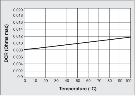
DCR varies with temperature in the same manner as the resistivity of the winding material, typically copper. It is important that the DCR rating makes note of the ambient test temperature. The temperature coefficient of resistance for copper is approximately +0.4% per degree C3. So the part shown rated at 0.009 Ohms max would have to have a corresponding rating of 0.011 Ohms max at 85°C, only a 2 milliOhm difference in this case, but a total change of about 25%. The expected DCR versus temperature is shown in Figure 4.

Doc469-Figure-4.gif
Figure 4. Expected DCR Based on 0.009Ω Max at 25°C

AC Resistance

This is a parameter that is not commonly shown on inductor data sheets and is not typically a concern unless either the operating frequency or the ac component of the current is large with respect to the dc component.

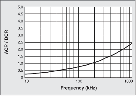
The resistance of most inductor windings increases with operating frequency due to skin effect. If the ac or ripple current is relatively small compared to the average or dc current then the DCR gives a good measure of the resistive loss to be expected. The skin effect varies with wire diameter and frequency3, so to include this data would require a full frequency curve for each inductor listed in a catalog.

Doc469-Figure-5.gif
Figure 5. ACR/DCR for #22 AWG Round Copper Wire

This has not been necessary for most applications working below 500 kHz. As can be seen from Figure 5 the ac resistance does not become comparable to the dc resistance at frequencies below about 200 kHz. And even above that frequency the ac resistance will not be an issue if the ac current is not large compared to the dc component. Nevertheless at frequencies above 200-300 kHz it is recommended to ask the supplier for loss versus frequency information to supplement the published information.

The designer should try to choose the component that has the largest possible resistance if the size of the component is to be minimized. Typically to reduce the DCR means having to use larger wire and probably a larger overall size. So optimizing the DCR selection means a tradeoff of power efficiency, allowable voltage drop across the component, and component size.

Self Resonant Frequency (SRF)

Every inductor winding has some associated distributed capacitance which, along with the inductance forms a parallel resonant tank circuit with a natural self-resonant frequency. For most converters it is best to operate the inductors at frequencies well below the SRF. This is usually shown in the inductor data as a “typical” value.

Current Rating

Current Rating is perhaps the rating that causes the most difficulty when specifying a power inductor. Current through a dc-dc converter inductor is always changing throughout the switching cycle and may change from cycle to cycle depending on converter operation, including temporary transients or spikes due to abrupt load or line changes. This gives a constantly changing current value with sometime a very high peak-to-average ratio. It is the peak-to-average ratio that makes specification difficult. If one takes the highest possible instantaneous peak current and looks for an inductor with this “current rating” the inductor is likely to be overkill for the application, yet if one looks for a current rating for the average current, the inductor may not perform well when passing the peak current. The way to address this problem is to look for an inductor that has two current ratings, one to deal with possible core saturation from the peak current and one to address the heating that can occur due to the average current.

Saturation Current

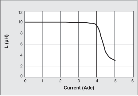
One effect of current through an inductor is core saturation. Frequently dc-dc converters have current wave shapes with a dc component. The dc current through an inductor biases the core and can cause it to become saturated with magnetic flux. The designer needs to understand that when this occurs the inductance drops and the component no longer functions as an inductor. Figure 6 shows a typical L vs current curve for a gapped ferrite core. It can be seen that this curve has a “knee” as the inductor moves into the saturation region. Definition of where saturation begins is therefore somewhat arbitrary and must be defined. In the example of Table 1, saturation is defined at the point at which the inductance drops by 10%. Definitions in the range of 10-20% are common, but it should be noted some inductor catalogs may use figures of 50% inductance drop. This increases the current rating but may be misleading as far as the usable range of current is concerned.

Doc469-Figure-6.gif
Figure 6. L vs DC Bias Current for Coilcraft DO3316P-103

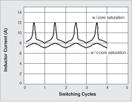
Inductor core saturation can often be observed directly in the converter current waveform where di/dt is inversely proportional to inductance. As inductance drops due to core saturation, the current slope increase rapidly. This can cause noise and damage to other components.

If the inductor is operated at currents only slightly exceeding the saturation current rating, however, the problem may not be so dramatic. In many cases a slight rise in the slope of the current waveform is acceptable. Despite the potential pitfalls, it is typically desirable to operate with current peaks near the saturation rating because this allows the smallest possible inductor to be chosen. Increasing the saturation current rating typically means using a larger size component or selecting a smaller inductance value in the same size.

Doc469-Figure-7.gif
Figure 7. Inductor Current Waveform With and Without Core Saturation.

RMS Current

The second major effect of current is component selfheating. The RMS current is used to give a measure of how much average current can continuously flow through the part while producing less than some specified temperature rise. In this case the data sheets almost always provide a rating based on application of dc or low frequency ac current, so this does not include heating that may occur due to skin effect as mentioned earlier or other high frequency effects. The current rating may be shown for a single temperature rise point as in the example, or some suppliers provide helpful graphs of temperature rise versus current or factors that can be used to calculate temperature rise for any current.

The Irms rating should include the ambient temperature at which it was measured. Normally an inductor specification includes an operating temperature range. This is the range of ambient temperature environment within which the inductor is expected to be used. Temperature rise due to self heating may cause the inductor to be at a temperature higher than the rated range. This is normally acceptable provided the insulation ratings are not exceeded. Most inductors presently use at least 130°C or 150°C insulation types.

As with other parameters it is important to know the inductor temperature rise so this can be traded off with other parameters when making design choices. If lower temperature rise is desired, a larger size component is most likely the answer.

Conclusion

It can be seen that inductors for dc-dc converters can be described by a small number of parameters. However each rating may be thought of as a “snapshot” based on one set of operating conditions which may need to be augmented to completely describe expected performance in application conditions. Table 2 summarizes the ratings that should appear in a power inductor data sheet.

References

  1. Switchers Made Simple, an Expert System for the Automated Design of DC to DC Converters using Simple Switcher Power Converters Version 4.1, National Semiconductor.
  2. Magnetics for RF, power, filter and data applications, p32, Coilcraft Inc, Cary, IL, USA, June 2013.
  3. Reference Data for Radio Engineers 6th Edition, Howard W. Sams & Co., Inc, Indianapolis, Indiana, USA, 1975.
  4. McLyman, Colonel William T., Designing Magnetic Components for High Frequency dc-dc Converters, Kg Magnetics, Inc. San Marino, CA, USA, 1993.
Table 2. Summary of Important Inductor Ratings
Parameter Rating Should Include
Inductance
  • Nominal value
  • Tolerance
  • Test frequency
  • Test voltage
  • Ambient test temperature
DCR: The wire resistance.
  • Nominal with tolerance or max value
  • Ambient test temperature
SRF: The frequency at which the winding self capacitance resonates with the inductance.
  • Typical or nominal value
Isat: The current at which inductance drops due to core saturation.
  • Minimum or typical value.
  • Definition of saturation.
Irms: The current which causes a specified amount of temperature rise.
  • Minimum value.
  • Ambient test temperature
Doc 469

Questions or Concerns?

Ask View FAQs


General Applications

Handling and Processing

RF Inductors

Power Conversion

EMI/RFI Filtering

Special Applications