LED lighting is an exciting and fast growing application. LEDs can provide low cost, reliable lighting for a wide variety of applications ranging from architectural and automotive to signage and handheld devices. The designer faces the challenge of choosing from a vast array of LED manufacturers and device styles. Equally challenging can be the selection of components for the LED driver circuit. Fortunately, powerful tools are available that greatly facilitate the power inductor selection.
Since LED applications can use LEDs individually as well as parallel or serial arrays, the driver circuit may need to be a voltage step-up, step-down, or both. The Coilcraft DC-DC Optimizer tool (https://www.coilcraft.com/en-us/ tools/dc-dc-optimizer/#/search) can be used to select the inductor for all of these driver circuit configurations.
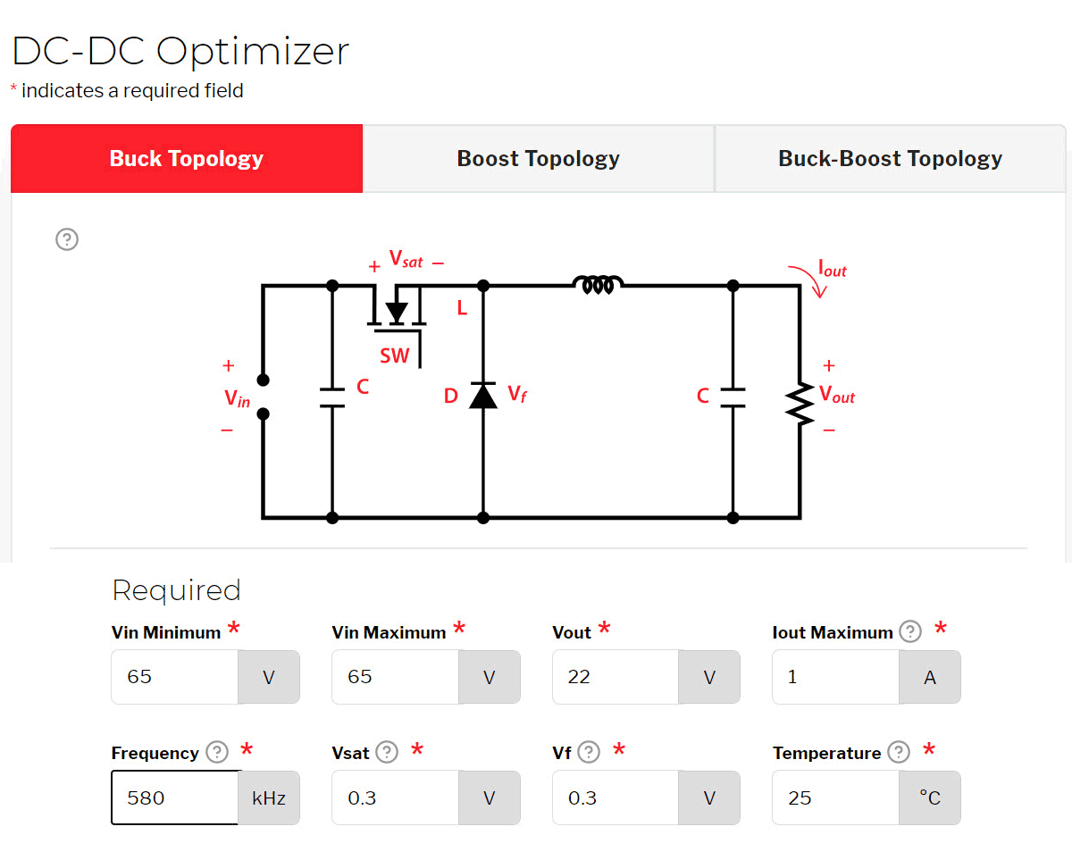
This example demonstrates the use of the Coilcraft DC-DC Optimizer tool to select the inductor for a Texas Instruments Buck LED driver reference design based on the LED Driver TPS92515-Q1. This design is for a high-brightness LED and features a wide input voltage, PWM dimming, and an analog dimming capability.
The design has a switching frequency of 125 kHz and an input voltage of 5.5 to 65 V. Electrical performance specifications are:
Fsw = 125 kHzThis is all the information needed to proceed to the Coilcraft DC-DC Optimizer tool. The first step is to identify Buck as the driver circuit topology.
Table 1. Typical White LEDs
Company | Part Number | Vf (V) | Io (mA) | Color | Url |
---|---|---|---|---|---|
Nichia | NJSW170C | 3.0 | 350 | White | www.nichia.com |
Osram Opto | KW DPLS31.SB | 3.05 | 120 | White | www.osram.com |
Everlight | A09K-C71501H-AM | 3.1 | 150 | Cool White | www.everlight.com |
Samsung | SPMWHT346EA3 | 3.5 | 140 | White | www.samsung.com/led/ |
Seoul Semiconductor | SZ8-Y11-W0 | 2.8 | 150 | White | www.seoulsemicon.com |
Cree | JE2835 3V | 3.0 | 150 | White | www.cree.com |
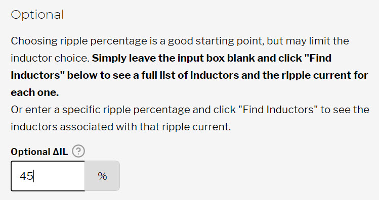
The second step requires inputting the operating parameters: Vin, Vout, Iout, switching frequency and the selection of the allowed peak-peak ripple current.
Note the input voltage as well as the output current and voltage are specified as part of the design requirement. The switching frequency may represent some design freedom if a driver IC is not yet selected, but generally the only degree of freedom in selecting the inductor value is the amount of ripple current to be allowed.
As the default setting, the DC-DC Optimizer tool calculates the ripple current for each inductor in the tool. As an option, a specific ripple percentage can be entered into the tool. In this example, the design uses a 1 Amp solution with 45% peak-peak inductor ripple current.
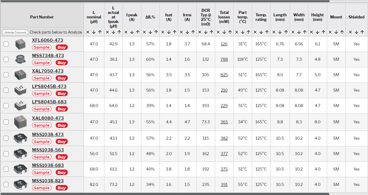
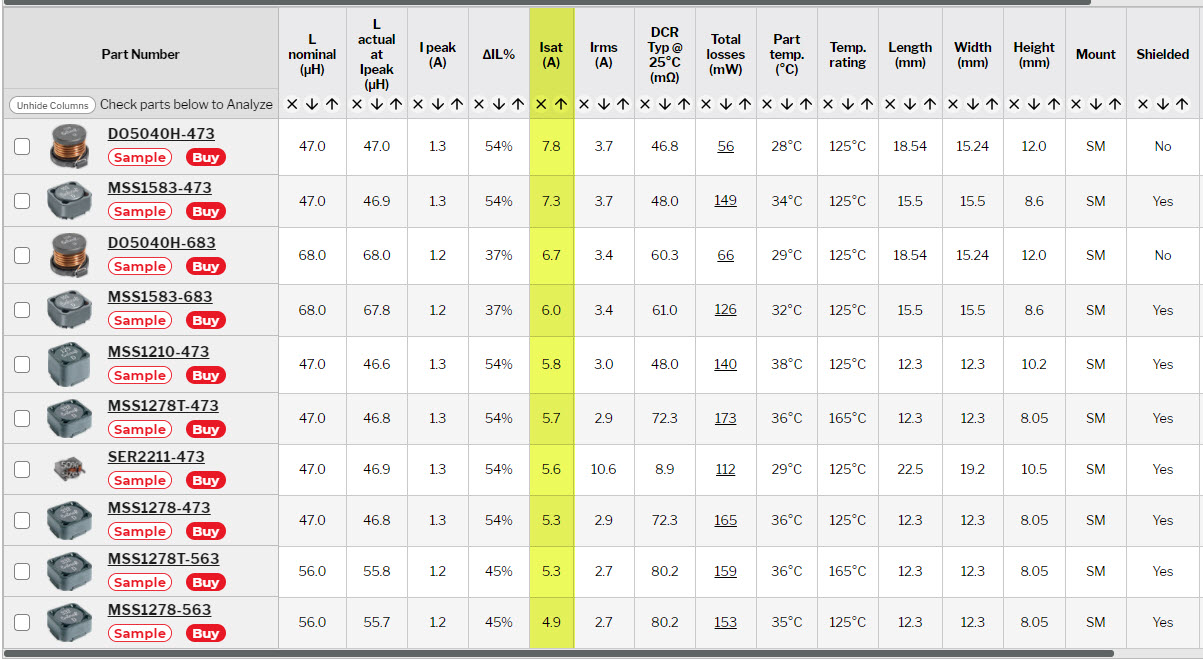
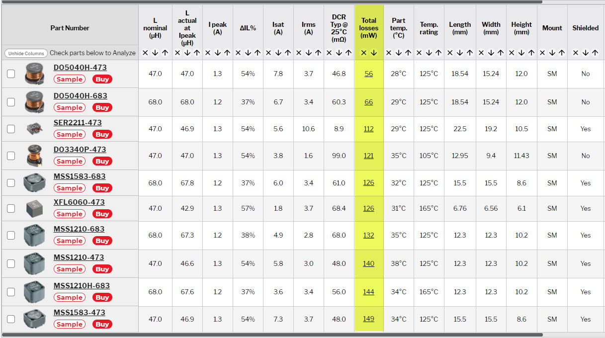
From these inputs, the Coilcraft DC-DC Optimizer tool calculates the resulting ripple current for each inductor in the tool within a range of the entered ripple current.
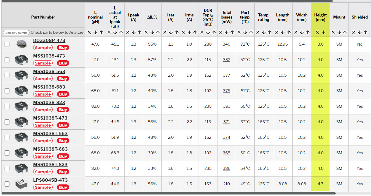
With multiple results, the user may optimize the inductor selection based on criteria specific to the application. The tool allows a quick sort of the results by user-selected parameters. For example, for a handheld mobile device or backlight display, component height may be the most important criterion.
If extra margin in the current rating to prevent inductor saturation is preferred, sorting by Isat is recommended.
More importantly, you can sort by total loss (DC loss + AC loss) to select an inductor that provides the best power efficiency for your application.
The Coilcraft DC-DC Optimizer tool features the flexibility to help the user optimize the inductor selection based on the criteria most important to that application.
LED lighting is a growing and exciting application area and Coilcraft design tools can guide the designer quickly and easily to inductors best suited to a variety of applications.