High speed data interfaces like USB, HDBaseT™, HDMI, DVI, and DisplayPort require careful consideration to ensure reliable communication that is free of disruptive EMI. Of the many tools at the designer’s disposal like trace routing, termination and component placement, the common mode filter choke remains one of the most powerful. For the variety of signal sizes, thermal variations and spectral density in high speed communications, the common mode filter choke is an effective and widely used interface circuit component. Common mode chokes help maintain the integrity of high speed communications and may be necessary for FCC and international regulatory standards conformance. FCC CFR 47 applies generally to radio frequency devices (Part 15) and includes particular requirements for Industrial, Scientific and Medical Equipment (Part 18). In addition to required standards conformance, there may be other application-specific requirements. For example, major auto makers maintain their own EMI requirements for vehicles.
The optimal common mode choke for a particular application depends on many factors. The first step in choosing the best part is to select only those that will not adversely attenuate the differential signal.
The communication standard (see Table 1) determines the data rate and therefore the required bandwidth for the differential mode performance.
Table 1. Typical data rates
Signal Interface | Data rates |
USB2.0 (High Speed) | 480 Mbit/s |
USB3.1 Gen 1 (SuperSpeed)(former USB3.0) | 5 Gbit/s |
USB3.1 Gen 2 (SuperSpeed+) | 10Gbit/s |
HDMI® | 1.65 Gbit/s to 6 Gbit/s; |
HDBaseT | Upto 10.2 Gbit/s |
FireWire 800/S800T (IEEE1394b-2002/ IEEE1394c-2006) |
Up to 800 Mbit/s |
FireWire S1600/S3200 | 1.57 Gbit/s and 3.15 Gbit/s |
LVDS per ANSI/TIA/EIA-644-A | Up to 1.9 Gbit/s |
PCI Express® 2.0 | 500 Mbit/s |
SATA 1.0/2.0/3.0/3.1/3.2 | 1.5 Gbit/s;3 Gbit/s;6 Gbit/s;6 Gbit/s;16 Gbit/s |
DVI | Upto 3.96 Gbit/s |
DisplayPort | Upto 8.1 Gbit/s |
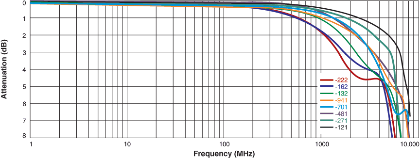
It is important, but relatively straightforward, to select a part with low differential mode attenuation within the signal frequency range. Figure 1 shows the -3dB differential mode cutoff frequency for Coilcraft’s 0805USBN Series, which is clearly above at 1GHz and up to 6.5GHz. Therefore distortion of the high frequency differential mode signal and its harmonic can be kept at a very small level, making our 0805USBN parts suitable for typical USB3.1 Gen 1 data rates, as are our 0805USBF and 0603USB Series.
Figure 1. Differential mode attenuation for 0805USBN
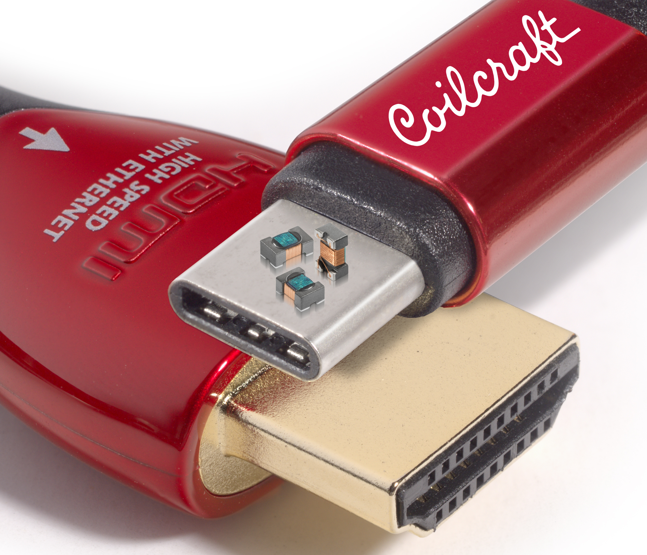
Figure 2. Coilcraft 0805USBN common mode chokes
Even though the differential mode performance is straightforward, and the requirement is predictable for a given data rate, the real focus should be on determining the required common mode performance. The amount of filtering required also depends on the data rate, but is harder to predict because of all the possible physical aspects of the application that may affect the amount of undesirable EMI generated. Design considerations such as impedance matching, connector pin impedance, trace widths and shielding may impact the final design.
As illustrated below, common mode chokes impede noise common to both lines by flux addition when connected as shown. In differential mode the flux cancels and the desired signal is not attenuated.
When a challenge does arise, it is important to identify the right solution. One easy choice is to identify application-specific chokes; that is, filter chokes that have been designed with specific applications in mind, like the Coilcraft line of USB common mode chokes.
Since real world EMI challenges do not always fit nicely into pre-arranged solutions, ready access to filter performance data is key. Selecting the appropriate common mode choke has been simplified with Coilcraft’s online Common Mode Choke Finder tool at: www.coilcraft.com/ en-us/tools/common-mode-choke-finder/#/search.
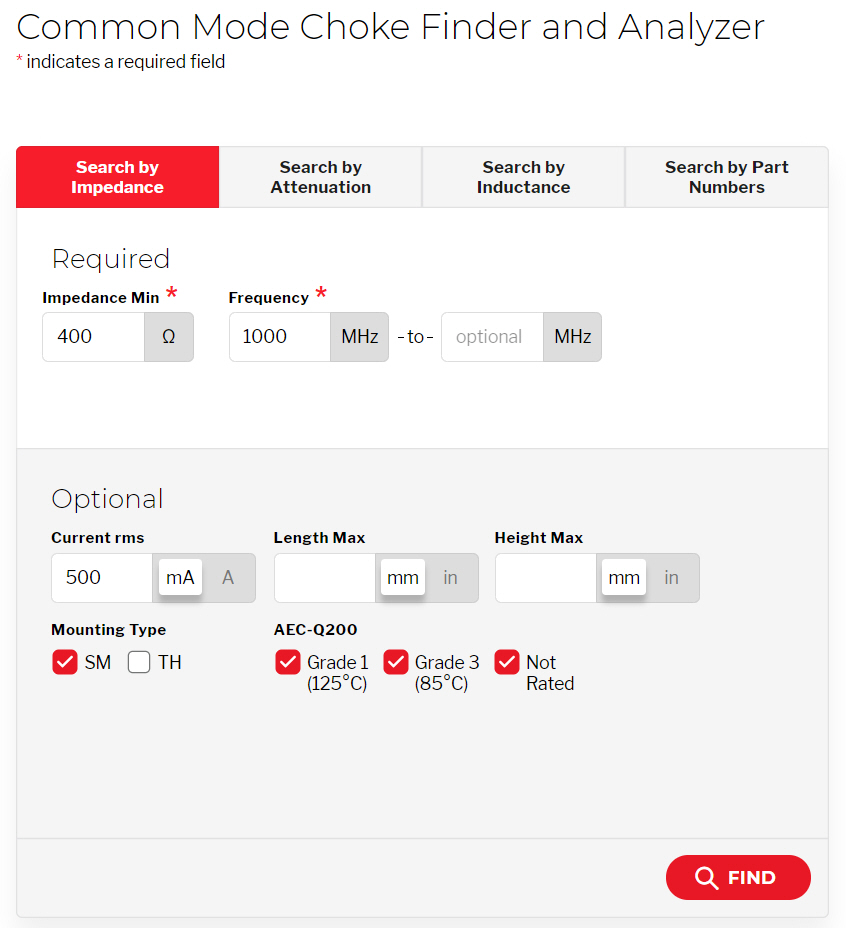
To start, you specify the filtering requirements of your application: the desired amount of impedance or the attenuation at a particular frequency (or frequency range). Alternatively, if a specific inductance value has already been identified, the tool can search from that input as well.
From this information the tool searches a wide database and presents the best solutions. All of the recommended common mode chokes are presented in a sortable table (see Figure 3) that includes all the pertinent specifications and actual size photos. The table is initially listed with the smallest size (shortest length) parts at the top. You can then sort the results by other specifications such as impedance or attenuation, current rating, height, and many other characteristics. Pricing information is also included in the table.
Figure 3. Coilcraft Common Mode Choke Finder and Analyzer search results page
One of the most powerful capabilities of this tool is the ability to compare up to 6 different filters on the same graph, making direct, side-by-side comparisons between products much easier. Impedance and attenuation curves are shown for each selected part over the desired frequency range (Figure 4). By moving the cursor over the curves, users can see the exact data point at any frequency of interest via a small pop-up window.
Figure 4. Coilcraft Common Mode Choke Finder and Analyzer side-by-side comparison graphs
Coilcraft’s Common Mode Choke Finder is the most sophisticated and easy-to-use online tool available in the industry. It is a great supplement to the development of your EMI filter design projects, making your common mode chokes selection effective and efficient.
Of course you can also search the old fashioned way by browsing web pages. We’ve also made this easier by collecting all our common mode chokes on one handy page: www.coilcraft.com/en-us/products/emi/.