Site Settings

Warehouses
Language settings
Currency settings
Resources
Video Library
Cx Family Common Mode Chokes
0402CT Low Profile Chip Inductors
XAL7050 High-inductance Shielded Power Inductors
XGL4020 Ultra-low DCR Power Inductors

S-parameters for High-frequency Circuit Simulations

When to Use S-parameters for High-frequency Circuit Simulations

Scattering parameters (S-parameters) are frequency-domain reflection-transmission measurements, or models, that are used to simulate inductors, wideband transformers, and common mode chokes at RF and microwave frequencies. S-parameters can accelerate the simulation process by placing a single “black box” element into a schematic and pointing to a file. This avoids having to create complicated lumped-element (SPICE) model schematics that only approximate distributed characteristics. While easier to set up in simulation, users should understand the challenges and limitations of using S-parameters before analyzing simulation results. In this note, we will discuss the basics of S-parameters and when they are appropriate for circuit simulation.

What are S-parameters?

S-parameters are a complex matrix of numerical values typically arranged in the standard Touchstone format. The Touchstone format is a defacto industry standard that facilitates measurement and simulation using any instrument or simulation program that uses S-parameters. Touchstone parameters may be in an amplitude (magnitude) and phase (angle) format, or in a transmission and reflection coefficient S-parameter format. A 2-port device has (22=) four S-parameters, 3-port has (32 =) nine S-parameters, and a 4-port device has (42 =) sixteen S-parameters at each measured frequency. To distinguish the number of ports easily, Touchstone files use a file extension naming convention of .SNP where N is the number of ports (e.g. 2-port files end in .S2P, 3-port end in .S3P, etc.).

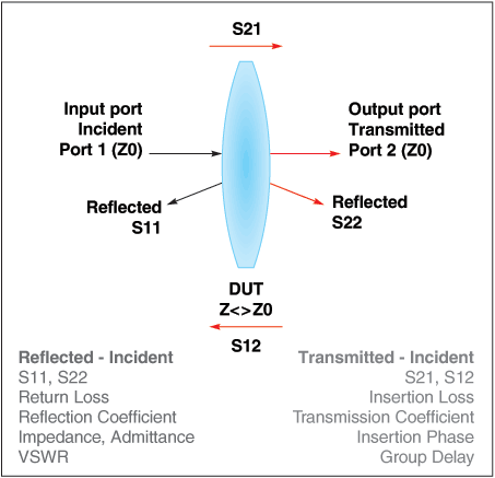
To better understand how S-parameters are measured, and what they represent, let’s use the analogy of a light wave impacting a lens. As illustrated in Figure 1, most of the light wave incident upon a lens is transmitted through the lens, but some is reflected back from the lens. The index of refraction, analogous to impedance mismatch, determines how much light is reflected back from the lens.

When measuring S-parameters, the instrument sends a power wave down the measurement cable at a specified frequency. When the wave encounters the device under test (DUT) any impedance mismatch creates some reflected energy. The instrument — typically a vector network analyzer — records the incident, transmitted and reflected energy, and converts the amplitude and phase information to S-parameters. Network analyzers can sweep S-parameters across a very wide range of frequencies. The results can be converted back to impedance and phase characteristics of the DUT over the measured bandwidth using simulation programs (or by hand if you enjoy doing complex matrix math).

Numbering Convention and Meaning

To understand the numbering convention and meaning of S-parameters, let us look at a 2-port example. For a 2-port s-parameter file, there are four S-parameters: S11, S12, S21, and S22. The numbering convention uses the 1st number after the S as the port where the signal emerges (the output port) and the 2nd number as the port where the signal is applied (the input port). Therefore, S11 and S22 are reflection coefficients, and S21 and S12 are transmission coefficients. Reflection (S11, S22) relates to return loss, impedance (admittance) and VSWR. Transmission (S21, S12) relates to insertion loss (gain/loss), phase, and group delay.
 
Doc1721-Fig1-light-wave-analogy.gif
Figure 1. Light Wave Analogy
 

When to Use S-parameters

Impedance analyzer measurements of inductors are made to an upper frequency of 3 GHz. When using an accurate phase calibration standard and good calibration and fixture compensation techniques, impedance analyzer measurements of inductance (L) and Q factor (Q) are the most accurate possible. Impedance analyzer measurements are essentially 1-port measurements, typically in the form of L and Q factor or impedance (Z) and phase values. Most RF and microwave inductors have L and Q specified at frequencies ≤250 MHz.

Many RF and microwave inductors have a self-resonant frequency (SRF) above the 3 GHz limit of impedance analyzers. When performance above 3 GHz is required, a vector network analyzer can be used to measure S-parameters at frequencies as high as 40 GHz. Network analyzers use the transmission-reflection measurement method and report results in the form of S-parameters.

Challenges and Limitations of S-parameters

As the frequency of an electrical wave increases, the wavelength decreases. Therefore, in order to have high measurement precision as the frequency increases, we need higher physical precision for the measurements, calibration standards, and fixtures. In effect, a small error in the physical length of a fixture or calibration trace will lead to larger measurement error as frequency increases.

At the high RF and microwave frequencies at which S-parameters are measured, printed circuit board (PCB) parasitics become increasingly involved. If a test fixture is not representative of the intended circuit at those higher frequencies, the measured performance will not agree with that of the intended circuit.

Adding PCB parasitics to fixture de-embedded S-parameter measurements for simulation requires care and experience. The most accurate method of obtaining circuit-specific S-parameters is to measure them using the intended PCB and layout. The next best method is to use global substrate-scalable models, such as those developed by Modelithics.

S-parameters are small-signal measurements (or based on small-signal models) that have no bias current applied. Therefore, S-parameters should not be used for large-signal loss or saturation modeling of inductors, chokes, or transformers. Saturation is typically not a concern with open-magnetic-constructed (non-magnetically shielded) RF and microwave inductors and chokes, or with wideband RF transformers when used within the published current rating.

Coilcraft S-parameters

Coilcraft has published measurement-based S-parameters for our RF- and microwave-frequency inductors (chip inductors and air core inductors), RF chokes, wideband RF transformers, and high-speed common mode chokes. The S-parameter data files represent de-embedded 50 Ohm measurements unless otherwise indicated. Because a variety of customer-chosen PCB materials, thicknesses, and board layouts are possible, effects due to circuit board traces, board materials, ground planes, or interactions with other components are necessarily not included.

Our RF inductor S-parameters are produced by creating a lumped element (SPICE) model that best matches a representative sample of measured inductors. The S-parameters are then generated from the model using software. Because our RF inductor S-parameters are generated from our models, they offer the advantage of ease of use vs. SPICE models. A “readme” file is included with each zip file for a series, describing the measurement conditions.

The simulated SRF of our S-parameter inductor models will be higher than that of a measurement of the inductor mounted on a circuit board, due to fixture de-embedding. The parasitic reactive elements of a circuit board or fixture will lower the effective in-circuit resonant frequency, especially for very small inductance values. These can be added to the model, if known.

Because our inductor models are generated from a SPICE model that is typically valid up to near the SRF, they capture the 1st resonance and no higher-order parasitic effects. Meaningful simulations of higher-order effects require substrate interactions, which are best captured by a measurement on the intended PCB or a Modelithics substrate-dependent model using the intended PCB characteristics.

S-parameters for Coilcraft wideband RF transformers and high-speed common mode chokes are made by measuring a typical part from a representative sample. The published S-parameters represent de-embedded measurements as described in the individual “readme” file for the applicable series.

Conclusion

Understanding the meaning of S-parameters, how they are measured, and their limitations can lead to more meaningful simulations of RF- and microwave-frequency inductors, chokes, wideband RF transformers, and high-speed common mode chokes. This document describes how Coilcraft S-parameters are generated, and how to best apply them to your simulations.

Sources:

Keysight, S-Parameter Measurements (Basics for High Speed Digital Engineers), White Paper
Doc1721

Questions or Concerns?

Ask View FAQs


General Applications

Handling and Processing

RF Inductors

Power Conversion

EMI/RFI Filtering

Special Applications