Site Settings

Warehouses
Language settings
Currency settings
Resources
Video Library
Cx Family Common Mode Chokes
0402CT Low Profile Chip Inductors
XAL7050 High-inductance Shielded Power Inductors
XGL4020 Ultra-low DCR Power Inductors

Power-handling Capabilities of Inductors

Current, Power and Temperature Rise

Inductors are not typically rated by power, however an approximation of the power-handling capability of an air core or ceramic core chip inductor can be estimated using the data sheet specifications for current and resistance.

Example: An 1812CS-102XJL, 1 µH, chip inductor has an Irms rating of 480 mA and a maximum DCR rating of 1.2Ohms. The Irms rating corresponds to a 15°C temperature rise above ambient. The maximum allowed ambient temperature is 125°C, so the 15°C temperature rise allows for a maximum part temperature of ~(125 + 15) = 140°C.

To estimate the power capability, calculate Irms2 × DCR. If we assume that the nominal DCR is 80% of the maximum DCR specified, the calculation is:

(0.48 A)2 × (0.8 × 1.2 Ohms) = 0.221 W = 221 mW.

Therefore, approximately 221 mW of power causes the temperature of this inductor to rise ~15°C.

At RF frequencies, the ESR is much higher than the DCR. Therefore, the amount of current that causes the same temperature rise is significantly reduced. For example, if the RF signal is 100 MHz, the ESR of the inductor is 8.14 Ohms (almost seven times the DC resistance) so the Irms AC current that corresponds to the same power (and thus temperature rise) is only ~161 mA as opposed to the 480 mA rating at DC. This estimate may be in error if there are current-dependent losses in the inductor or other loss mechanisms at higher frequency that are not part of the low-current ESR measurement.

Power dissipated by the inductor

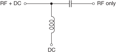
The purpose of the inductor in a bias tee, as shown in the figure below, is to provide a DC bias to the amplifier while blocking the high frequency RF signal from entering the DC source. Ideally, any RF signal applied to the bias line is filtered out by the series inductor. For this discussion, we assume a lossless (e.g. air core or ceramic core) inductor for which only (AC and DC) copper losses exist – no core losses.
 
Doc-1066-schematic.gif
Equivalent Circuit of a Bias Tee

The total DC power dissipated by the inductor is:

Pdc = Idc2 × DCR

The total AC power dissipated by the inductor is:

Pac = Irms2 × ESR

where:
Idc is the DC current through the inductor.
Irms is the magnitude of the AC (RF signal) current through the inductor (likely low if the inductor is nearly ideal).
DCR is the DC resistance of the inductor.
ESR is the effective series resistance of the inductor at the frequency of the RF signal (assuming only a single RF frequency).

The total (DC and AC) power dissipated by the inductor is:

Ptotal = Pdc + Pac
or
Ptotal = Idc2 × DCR + Irms2 × ESR

As illustrated, in the simplest case of a single frequency AC signal on the on the RF line, in order to determine the AC power dissipated by the inductor, the ESR of the inductor at the RF frequency, and the Irms value of the RF current through the inductor, must be known. For more complicated multi-frequency noise signals to be filtered, the total AC power dissipated by the inductor is the sum of all Irms2 × ESR contributions, where ESR varies for each contribution by frequency.

Wideband RF chokes

The broadband performance of wideband RF chokes is the result of using high permeability core materials such as powdered iron or ferrite. With RF signals traveling through the inductor, frequency-dependent and current-dependent core losses contribute additional heat to the total produced by the inductor. A simple ESR measurement (typically made at very low current) will not capture these losses. Therefore the above estimation method is not applicable and incorrectly predicts a lower temperature rise than will actually result. The inductor will get hotter than expected. The same is true for any inductor that has a high permeability (ferrite, powdered iron, composite) core. In the case of high-perm core products, we suggest making a temperature rise measurement of the inductor under all conditions of frequency and current that may result in your application to determine the worst-case temperature rise.
Doc 1066

Questions or Concerns?

Ask View FAQs


General Applications

Handling and Processing

RF Inductors

Power Conversion

EMI/RFI Filtering

Special Applications