Site Settings

Warehouses
Language settings
Currency settings
Resources
Video Library
Cx Family Common Mode Chokes
0402CT Low Profile Chip Inductors
XAL7050 High-inductance Shielded Power Inductors
XGL4020 Ultra-low DCR Power Inductors

Operating Voltage for Inductors

Considerations for Inductor Selection

Introduction

Voltage ratings are often specified for many electronic components, including capacitors, resistors and integrated circuits, but traditionally this has been rare for inductors. Recent trends, particularly the introduction of higher voltage rated semiconductor devices, have created a new emphasis on operating voltage as part of the inductor selection process. Inductors once considered optimized for high current, low voltage applications are finding homes in new designs that apply higher voltage stress to the inductor.

Reasons can be suggested for why voltage ratings have not been a common concern for single winding inductors. For one thing, steady state voltages above 42.4 V peak, or 60 V  dc voltages in computers and similar office equipment are generally considered hazardous. Circuits driven by higher voltages generally use transformer-isolated circuits, and the vast majority of single inductor dc-dc converters have therefore operated at much lower, non-hazardous voltages. Also, components such as silicon MOSFETs have traditionally been limited to low voltage operation both for achieving efficient operation as well as preventing breakdown within the device.

For the most part, consideration of inductor performance in application circuits has been more related to current than voltage. For dc-dc converter inductors, including those for processor core voltages, it is quite common to process relatively high currents of 100 A or more at relatively low voltages, from less than a volt to maybe a few dozen volts. In these applications it is generally well understood that one must consider inductor saturation current ratings and self-heating current ratings. Recent trends, such as replacement of silicon MOSFETs by gallium nitride (GaN) and silicon carbide (SiC), have enabled circuit operation directly from higher voltages, and newer energy sources such as 48 volt automotive batteries instead of traditional 12 volt systems have driven the need to more carefully consider inductor operating voltage.

Operating Voltage

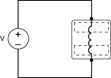
Operating voltage for an inductor is the voltage between the two inductor terminals as shown in Figure 1.
 
Doc1520-Figure_1_Operating_Voltage-01.gif
Figure 1. Operating Voltage

This operating voltage might come directly from a voltage source as shown, or might be generated at the inductor terminals as a result of circuit operation. In either case, inductor operating voltage must follow the relationship shown in Equation 1, which is derived from Faraday’s law of induction.
 
Doc1520-Equation1.gif
Equation 1. Inductor current-voltage relationship

Operating voltage, sometimes referred to as working voltage, is defined as follows in standards like UL60950:

Highest voltage to which the insulation or the component under consideration is, or can be, subjected when the equipment is operating under conditions of normal use.

Overvoltages that originate outside the equipment are not taken into account.1


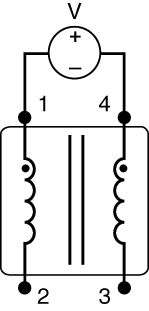
Operating voltage should not be confused with isolation or hi pot voltage shown in Figure 2 which is a measure of insulation strength between transformer windings or, say, between a winding and outer case. Isolation (hi pot) voltage must be considered separately, and is more appropriate for isolation transformers than single winding inductors.
 
Doc1520-Figure_2_Hipot_Iso_Transformer_Rev2.gif
Figure 2. Hipot measurement for isolation transformer

Operating Voltage Rating

Determining a meaningful, absolute max, one-sizefits-all voltage rating for inductors that are built using a variety of different core types and winding patterns has many well-known challenges, as discussed in Coilcraft Document 712 “Working Voltage Ratings Applied to Inductors”. Nevertheless, voltage ratings can be assigned to power inductors to provide meaningful comparisons and guidance in choosing the most appropriate inductor type.

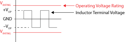
A voltage rating should specify the operating voltage that won’t damage inductor insulation. Because insulation damage can sometimes occur over time with repeated voltage application, the most conservative voltage rating should specify the maximum voltage that can be continuously or repeatedly applied to the inductor terminals without expectation of insulation damage. For example, for the square wave inductor voltage shown in Figure 3, an inductor should simply be chosen with an operating voltage rating equal to or greater than the square wave voltage.
 
Doc1520-Figure-3-Voltage_Rating.gif
Figure 3: Inductor Rating ≥ Expected Voltage

Coilcraft Operating Voltage Ratings

As an industry leader, Coilcraft has established operating voltage ratings for many of our power inductor series.

Check out our High Voltage Inductors for specific operating voltage ratings.

Please contact Coilcraft directly regarding voltage ratings for other inductor families. [email protected].

Assigning a conservative maximum operating voltage rating in this way means that it will often be the case that higher voltages can be applied for short durations without damage. Such voltages may occur in the form of occasional spikes or surge voltages. The capability of a specific inductor to withstand temporary over-voltages may be quite high and is not always directly related to the maximum continuous operating voltage rating. The ability to withstand high, temporary, surge voltages depends both on the specifics of the inductor construction as well as the magnitude, rise time, and specific waveshape of the high voltage.

For any question about the ability of a specific inductor to withstand high peak or surge voltages, the application conditions should be discussed with Coilcraft engineering to determine suitability of the inductor for the specific application.

References

1. UL 60950-1, Information Technology Equipment – Safety – Part 1: General Requirements, para 0.2.1, Underwriters Laboratories Inc. (UL) 333 Pfingsten Road Northbrook, IL 60062-2096
Doc 1520

Questions or Concerns?

Ask View FAQs


General Applications

Handling and Processing

RF Inductors

Power Conversion

EMI/RFI Filtering

Special Applications