Site Settings

Warehouses
Language settings
Currency settings
Resources
Video Library
Cx Family Common Mode Chokes
0402CT Low Profile Chip Inductors
XAL7050 High-inductance Shielded Power Inductors
XGL4020 Ultra-low DCR Power Inductors

Key Parameters for Selecting RF Inductors

Understanding RF Inductor Specifications

RF inductor selection involves these key parameters: mounting (surface mount or through-hole), inductance value, current rating, DC resistance (DCR), self-resonant frequency (SRF), Q factor, and temperature rating. While small size is typically desired, the laws of physics limit how small an inductor can be for a given application. Inductance value and current rating are the chief determinants of size; other parameters can then be optimized.

What determines my required inductance value?

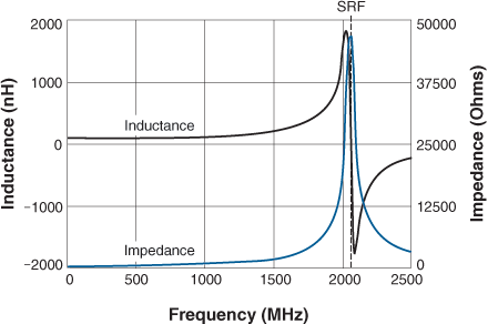
If the inductor is to be used as a simple one-element (1st order) high-frequency choke, the selection is based on the frequency of peak noise to be choked out. At the self-resonant frequency (SRF) of an inductor, the series impedance is at its maximum. So for a simple RF choke the selection is based on finding an inductor whose SRF is near the frequency where choking is needed.

For higher order filters, the inductance value for each element must be calculated based on the filter cutoff frequency (for low-pass and high-pass filters) or bandwidth (for bandpass filters). These calculations are frequently performed using commercial circuit simulation programs, such as SPICE, AWR’s Microwave Office, and Agilent’s Genesys or ADS.

For tuned circuits or impedance matching, a tight inductance tolerance is desirable. As shown in Table 1, wirewound inductors typically achieve tighter tolerances than multilayer or thick film type inductors.

TABLE 1

  Inductance(nH) Inductance tolerance Q at 900 MHz Current rating (mA)
Wirewound (Coilcraft 0402DC-2N8XGL) 2.8 2% 78 2100
Multilayer (TDK MLK1005S2N7ST) 2.7 11% 31 500
 
  Inductance(nH) Inductance tolerance Q at 900 MHz Current rating(mA)
Wirewound (Coilcraft 0402DC-68NXGL) 68 2% 54 400
Multilayer (TDK MLK1005S68NJT) 68 5% 20 150

How does my current requirement affect my selection?

Higher current requires larger wire or more strands of the same wire size to keep losses and temperature rise to a minimum. Larger wire lowers the DCR and increases the Q, but at the expense of larger part size and possibly lower SRF. The current ratings shown in Table 1 indicate that wirewound inductors are superior to multilayer inductors of the same size and inductance value.

Higher current capacity and lower DCR can be achieved by using a ferrite core inductor with a lower turn count. Ferrite, however, may introduce new limitations such as larger variation of inductance with temperature, looser tolerances, lower Q, and reduced saturation current ratings. Ferrite inductors with open magnetic structures, like Coilcraft’s LS series, will not saturate, even at full rated current.

It looks like my current requirement determines the DC resistance.

Current ratings and DCR are closely related. In most cases, if all other parameters are held equal, a larger part size is needed to decrease the DCR.

How high must the Self-Resonant Frequency be for the inductor to work?

SRF is defined by the equation:   Doc671-Equation1.gif

For choke applications, the SRF is the frequency that provides the best signal blocking. At frequencies below the SRF, impedance increases with frequency. At the SRF, impedance is at its maximum. At frequencies above the SRF, impedance decreases with frequency.

For higher order filter or impedance matching applications, it is more important to have a relatively flat inductance curve (constant inductance vs. frequency) near the required frequency. This suggests selecting an inductor with an SRF well above the design frequency. A rule of thumb is to select an inductor with an SRF that is a decade (10×) higher than the operating frequency. In general, the choice of inductance value typically determines the SRF and vice versa. The higher the inductance value, the lower the SRF, due to increased winding capacitance.

Inductance and Impedance vs. Frequency

Inductance and impedance rise sharply near an inductor’s self resonant frequency (SRF) as shown in Figure 1. For choking applications, choose an inductor whose SRF is at or near the frequency to be attenuated. For other applications, the SRF should be at least 10 times higher than the operating frequency.
.
Doc671-fig1.gif

Figure 1. Inductance and Impedance for a 100nH Wirewound Inductor

When is Q factor important?

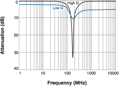
A high Q value results in a narrow bandwidth, which is important if the inductor is to be used as part of an LC tank (oscillator) circuit or in narrow bandpass applications. Refer to Figure 2. High Q also leads to low insertion loss, minimizing power consumption.

Doc671-fig2.gif

Figure 2. High Q Gives Narrow Bandwith and Low Insertion Loss


Q factor of an inductor is calculated from:   Doc671-Equation2.gif

All frequency dependent real and imaginary losses are included in the measurement of Q, including inductance, capacitance, skin effect of the conductor and core losses from the magnetic material. As indicated in Table 1, wirewound inductors have much higher Q values than multilayer inductors of the same size and value.

How do I select the temperature rating I need?

Power loss increases with current and DC resistance, causing the component’s temperature to rise. Inductors are typically rated for a specific ambient temperature and a temperature rise above ambient due to current through the inductor. For example, a part rated for 125°C ambient and a 15°C rise due to the full current rating (Irms or Idc) will have approximately a 140°C maximum part temperature. You only need to verify that your application ambient temperature and current draw do not exceed the inductor ratings.

How can I quickly search for inductors that have all of the characteristics I need?

Comparing data sheets of inductor manufacturers can be time consuming. Coilcraft’s RF Inductor/Choke Finder and Analyzer tool allows selection of inductors based on six different parameters. By entering just the inductance value and operating frequency, a list of all inductors that meet your requirements is presented.

Doc 671

Questions or Concerns?

Ask View FAQs


General Applications

Handling and Processing

RF Inductors

Power Conversion

EMI/RFI Filtering

Special Applications