Site Settings

Warehouses
Language settings
Currency settings
Resources
Video Library
Cx Family Common Mode Chokes
0402CT Low Profile Chip Inductors
XAL7050 High-inductance Shielded Power Inductors
XGL4020 Ultra-low DCR Power Inductors

Current and Temperature Ratings

Considerations for Current and Temperature Ratings

Introduction

This application note describes:
  • How to interpret Coilcraft inductor current and temperature ratings
  • Our current ratings measurement method and performance limit criteria
  • Calculations for estimating power performance limits based on current ratings
  • How to calculate component temperature from the temperature rating
  • How to estimate component DCR at temperatures other than 25°C.
  • How to calculate performance limits in pulsed waveform applications
  • Detailed rms calculations – Appendix A
  • Derivation of temperature rise equation – Appendix B
  • Conversion factors for various waveforms – Appendix C
Electrical ratings are interdependent. The current through a component depends on the applied voltage (waveform and duty cycle) and the component impedance. The impedance of a component depends on the DC resistance (DCR), the applied signal frequency (for AC resistance), and the component temperature. The temperature of a component depends on the thermodynamic (heat transfer) characteristics of the component, the circuit board, the solder connection, the surrounding environment, the impedance of the component, and the current through the component. The power dissipation of a component is a function of all of these variables.

The maximum operating rating of a component must be given in terms of a specific measurement method and performance limit. For example, the performance limit could be defined as exceeding a specified temperature rise or as a total breakdown of the insulation or wire. Different measurement methods and performance limit criteria lead to different conclusions. By establishing the method of measurement and the performance limit criteria, a baseline is set for evaluating each application.

Ultimately, circuit designers attempt to determine maximum operating limits for temperature, current, voltage, and power for each component. Each of these is specific to the application environment.

Coilcraft Inductor Current Ratings

Depending on the type of inductor (chip inductor, power inductor) we may specify an Isat, Irms, or IDC current.
  • Saturation current (Isat) is the current at which the inductance value drops a specified amount below its measured value with no DC current. The inductance drop is attributed to core saturation.
  • rms current (Irms) is the root mean square current that causes the temperature of the part to rise a specific amount above 25°C ambient. The temperature rise is attributed to I2R losses.
  • DC current (IDC) is the current value above which operation is not recommended without testing the component in its intended application.
For some inductors Isat is lower than Irms. The core saturates before the component temperature reaches the performance limit. In this case we may specify only the Isat as it is the limiting factor. For many inductors, Isat is higher than Irms. In these cases we may specify only Irms and the temperature rise above ambient. In many cases, we specify both Irms and Isat current to illustrate which measurement is more critical. IDC is specified typically when Irms greatly exceeds Isat.

Coilcraft Measurement Method and Performance Limit Criteria rms Current – Irms

We determine Irms by measuring the temperature rise above 25°C ambient caused by the current through a representative sample inductor. A low DC bias current is applied to the inductor, and the temperature of the inductor is allowed to stabilize. This process is repeated until the temperature rise reaches the rating limit. The measurements are taken with the sample inductor in still air with no heat sinking. The limit is typically a 15°C rise for chip inductors and a 40°C rise for power inductors.

Therefore, the current rating is based on the data sheet Irms current and temperature rise. The temperature rise of a component due to current depends on the ambient temperature. To determine the component temperature due to rated current at ambient temperatures above the data sheet ambient temperature, see the “Ambient Temperature Range” section of this application note.

Saturation Current – Isat

Isat ratings are established by measuring the inductance of a representative sample at a specific frequency with no DC current. The DC current level is then gradually increased and the inductance is measured.

The Isat rating is the current level at which the inductance value drops a specified amount (in percent) below its measured value with no DC current.

Power Limit Calculations

Total or “apparent” power (PA) consists of a combination of the average (real) power (Pavg) and the reactive (imaginary) power (Pvar). While the purely reactive portion of power does not consume energy, there is some loss associated with its transmission back and forth in the circuit because transmission lines are not perfect conductors.

Temperature rise due to the heating effect of current through an inductor is related to the average real power dissipated by the inductor. The average real power is a function of the effective series resistance (ESR) of the inductor and the rms current through the inductor, as shown in Equation 1.

Pavg = (Irms)2 × ESR     (1)
where:
Pavg = average real power in Watts
Irms = rms current in amps
ESR = effective series resistance in Ohms

Equation 1 can be used to estimate a power limit due to real losses. The real losses include DC and AC losses, and are described by the ESR of the inductor. The AC losses are frequency-dependent, therefore, we recommend using our simulation models to determine the ESR for calculating the real power dissipation at your specific application frequency.

The apparent (total) power required by an inductor is a function of the rms current through the inductor, the rms voltage across the inductor, and the phase angle difference between the voltage and current. Equation 2 can be used to estimate the apparent power required for the inductor.

PA = Irms × Vrms × cos (θ)     (2)
where:
PA = apparent power in Watts
Irms = rms current in amps
Vrms = rms potential across inductor in Volts
θ = phase angle in degrees

Since the AC behavior of an inductor is frequency dependent, and Vrms is application-specific, we recommend using our simulation models to determine the apparent power requirements for your specific application voltage and frequency.

Ambient Temperature Range

Ambient temperature is described as a range, such as “–40°C to +85°C.” The range describes the recommended ambient (surrounding environment) temperature range of operation. It does not describe the temperature of the component (inductor). The component temperature is given by Equation 3:

Tc = Ta + Tr × 0.00393 × (229.5 + Ta)     (3)
where:
Tc is the component temperature
Ta is the ambient (surrounding environment) temperature
Tr is the data sheet temperature rise due to rated current through the inductor

Refer to Appendix B for the derivation of this equation.

Example: The ambient temperature range for a power inductor is stated as –40°C to +85°C, and the Irms is rated for a 40°C rise above 25°C ambient.

The worst-case component temperature would be (85°C + 49.4°C) = 134.4°C at the Irms current

DC Resistance vs. Temperature

Equation 4 can be used to calculate the approximate DC resistance of a component within the operating temperature range:

DCRT2 = DCR25 × ((1 + 0.00393(T2 − 25))     (4)

where:
DCRT2 is the DC resistance at the temperature T2
DCR25 is the data sheet value of DC resistance at 25°C
T2 is the temperature in °C at which the DC resistance is being calculated

Pulsed Waveforms

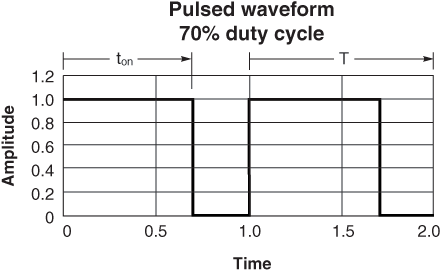
An ideal pulsed waveform is described by the period (T = 1/ frequency), amplitude, pulse width (ton), and duty cycle, as shown in Figure 1. Ideal pulsed waveforms are rectangular. Real pulsed waveforms have rise time, fall-time, overshoot, ringing, sag or droop, jitter, and settling time characteristics that are not considered in this discussion. We also assume that all pulses in a given application pulse train have the same amplitude.
 
Doc361-Fig1-Pulsed_70percent.gif
Figure 1

The duty cycle (D) is the ratio of the pulse width (time duration) to the pulse period, as shown in Equation 5.
D = ton / T       (5)
where:
D = duty cycle
ton = pulse width in seconds, T = period in seconds

Duty cycle is typically given as a percent of the period. For example, continuous waves have a 100% duty cycle, since they are “on” for the whole cycle. Square waves have a 50% duty cycle: “on” for a half cycle and “off” for a half cycle. Duty cycle can also be stated as a ratio. A 50% duty cycle is the same as a 0.50 duty cycle ratio.

To convert to pulsed power values from the equivalent continuous (100% D) waveform estimated power, equate the calculated energy values for a cycle, and solve the equation for the pulsed power. The calculation uses the definition: energy = power × time.

Energy = Pavg × T     (6)

For one cycle of a continuous (100% duty cycle) waveform, and invoking Equation 1:

Energy = (Irms)2 × ESRc × T
where:
ESRc = effective series resistance to continuous current

The ESR is frequency-dependent, and can be obtained from our simulation model of the chosen inductor.

For one cycle of a pulsed waveform,
Energy = Ppulsed × ton     (7)
Energy = (Ipulsed)2 × ESRpulsed × ton
where:
Ppulsed = equivalent pulsed power
ton = pulse width in seconds
ESRpulsed = effective series resistance to the pulsed current

While the pulse width (ton) and the pulsed current amplitude (Ipulsed) are defined for a specific application, the above logic requires either knowledge of ESRpulsed or the assumption that it is equivalent to ESRc. For the purposes of this discussion, we assume that ESR is frequency-dependent, but not waveform-dependent, therefore ESRpulsed = ESRc. With this assumption, equating the energy terms of Equation 6 and Equation 7, and canceling the ESR terms:
(Irms)2 × T = (Ipulsed)2 × ton     (8)
(Irms)2 / (Ipulsed)2 = ton / T     (9)
and since D is ton / T,
(Irms)2 / (Ipulsed)2 = D

Solving for the equivalent pulsed current,
Ipulsed = ((Irms)2 / D)0.5     (10)

Example: A chip inductor has an Irms rating of 100 mA for a 15°C rise above 25°C ambient. The duty cycle for a particular application is calculated using Equation 5 to be 30%.

Using Equation 10,
Ipulsed = ((0.1 A)2 / 0.30)0.5
Ipulsed = 0.183 A or 183 mA

This calculation predicts an equivalent 15°C rise above 25°C ambient for the 183 mA current pulse at 30% duty cycle.

The previous calculations assume that, regardless of the pulse amplitude, width, and duration, if the same amount of energy calculated from the power rating is delivered to the component over a cycle, the component will dissipate the energy safely. There may be physical conditions that limit this assumption due to the heat dissipation characteristics of the component, the solder connection, the circuit board, and the environment.

In the previous example, if the duty cycle is reduced to 10%, the calculated pulsed current would be 316 mA, which is more than three times the rated rms current, although only applied for 1/10 of a cycle. Our current ratings are based on steady-state measurements, not on pulsed current waveforms. While the duty cycle assumption is valid in many cases, we have not verified our ratings for pulsed waveforms. Therefore, we recommend testing your specific application to determine if the calculation assumptions are valid.

Appendix A – rms Calculations

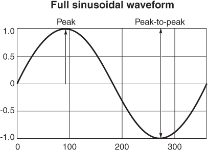
Figure 2 shows a typical sinusoidal waveform of alternating current (AC) illustrating the peak and peak-to-peak values. The horizontal axis is the phase angle in degrees. The vertical axis is the amplitude. Note that the average value of a sinusoidal waveform over one full 360° cycle is zero.
 
Doc361-Fig2-Full-Sinusoidal.gif
Figure 2

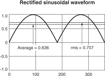
Figure 3 shows the same full sinusoidal waveform of Figure 2, full-wave rectified. The average rectified and rms values are illustrated for comparison.

Calculate the root-mean-square (rms) value by the following sequence of calculations: square each amplitude value to obtain all positive values; take the mean value; and then take the square root.
 
Doc361-Fig3-Rectified-Sinusoidal.gif
Figure 3

The rms value, sometimes called the “effective” value, is the value that results in the same power dissipation (heating) effect as a comparable DC value. This is true of any rms value, including square, triangular, and sawtooth waveforms.

Some AC meters read average rectified values, and others read “true” rms values. As seen from the conversion equation in Appendix B, the rms value is approximately 11% higher than the average value for a sinusoidal waveform.

Appendix B – Derivation of Temperature Rise Equation

Our current ratings are typically based on a specific temperature rise (Tr ) above 25°C ambient, resulting from the rated current. When a component is used in a higher ambient temperature environment, the resistance of the component wire is higher in proportion to the temperature difference between the higher ambient (Ta) and 25°C. The increase in resistance depends on the thermal coefficient of resistance (TCR) of the wire (α). For copper wire, α ≈ 0.00393. When full rated current is applied to the component at a higher ambient temperature, the increased wire resistance results in increased I2R losses. The increased losses are assumed to be converted to heat, resulting in a temperature rise that is proportional to the increase in resistance of the wire.

The derivation of the equation for determining the component temperature (Tc) when operating at a higher ambient temperature (Ta) follows. We begin with the definition of the temperature coefficient of resistance, using 25°C as our reference temperature.
 
α = ∆RR25 / (Ta – 25) = Ra - R25R25 / (Ta – 25)
∆RR25 = α (Ta – 25)

The increase in temperature due to the increased resistance = ∆RR25 × Tr

Tc = Ta + Tr + ∆RR25 × Tr
Tc = Ta + Tr (1 + ∆RR25 )
Tc = Ta + Tr (1 + α(Ta – 25))
Tc = Ta + αTrα + (Ta – 25))
For α = 0.00393
Tc = Ta + 0.00393 × Tr (229.5 + Ta)

Definitions:
∆R = Increase in resistance due to higher ambient temperature Ta
Ta = Ambient temperature (assumed to be >25°C)
Ra = Resistance of copper wire at ambient temperature (Ta)
R25 = Resistance of copper wire at 25°C ambient
Tr = Data sheet temperature rise due to rated current
Tc = Component temperature due to rated current at ambient temperature (Ta)

Appendix C – Conversion Factors for Various Waveforms

Use the following equations to convert between average, rms, peak, and peak-to-peak values of various waveforms of current or voltage.

Sinusoidal Waveforms

Given an Average Value:
rms = 1.112 × Average
Peak = 1.572 × Average
Peak-to-Peak = 3.144 × Average
Given an rms Value:
Average = 0.899 × rms
Peak = √2 × rms (≃1.414 × rms)
Peak-to-Peak = 2 × √2 × rms (≃2.828 × rms)
Given a Peak Value:
Average = 0.636 × Peak
rms = 1/ √2 × Peak (≃0.707 × Peak)
Peak-to-Peak = 2 × Peak
Given a Peak-to-Peak Value:
Average = 0.318 × Peak-to-Peak
rms = 1/(2× √2) × Peak-to-Peak (≃0.354 × Peak-to-Peak)
Peak = 0.5 × Peak-to-Peak

Squarewave Waveforms

Average = rms = Peak Peak-to-Peak = 2 × Peak

Triangular or Sawtooth Waveforms

Given an Average Value:
rms = 1.15 × Average
Peak = 2 × Average
Peak-to-Peak = 4 × Average
Given an rms Value:
Average = 0.87 × rms
Peak = √3 × rms (≃1.73 × rms)
Peak-to-Peak = 2 × √3 × rms (≃3.46 × rms)
Given a Peak Value:
Average = 0.5 × Peak
rms = 1/√3 × Peak (≃0.578 × Peak)
Peak-to-Peak = 2 × Peak
Given a Peak-to-Peak Value:
Average = 0.25 × Peak-to-Peak
rms = 1/(2 × √3) × Peak-to-Peak (≃0.289 × Peak-to-Peak)
Peak = 0.5 × Peak-to-Peak
Doc 361

Questions or Concerns?

Ask View FAQs


General Applications

Handling and Processing

RF Inductors

Power Conversion

EMI/RFI Filtering

Special Applications