The goal to create truly safe and high-performance autonomous vehicles has captured the imagination of the automotive industry and consumers alike. The rollout of such vehicles can seem quite close at times, and many industry resources are being devoted to their development. One particular sensing system that seems certain to play a key role is LiDAR, and companies are working to perfect these systems. Every area of the LiDAR system, including efficient DC/DC power supplies, must be optimized.
A LiDAR system may contain a half dozen or so power supplies, sometimes including Boost, SEPIC, Buck-Boost and even Flyback topologies. With so many required voltage rails, there is plenty of opportunity for optimization, and inductors or transformers will play a key role in almost all systems. Finding the inductor that fits best for each topology can be a challenge, but inductor suppliers are providing new tools and guidance to help this process.
Once a power supply topology and chipset are chosen, inductor selection can begin. Many electronic systems need to convert available voltages up and down to suit subsystem needs. LiDAR in particular requires automotive battery voltages to be converted up to drive the LiDAR transducers. The LM5001 switching regulator from Texas Instruments can be used to control Flyback, SEPIC or Boost converters, making it very useful for required LiDAR power rails.
For example, in its AN-1956 application note, Texas Instruments includes a reference circuit demonstrating a boost converter using a 100 µH inductor capable of 1.8 A of current. A major step toward optimizing the power converter is selecting the correct inductor.
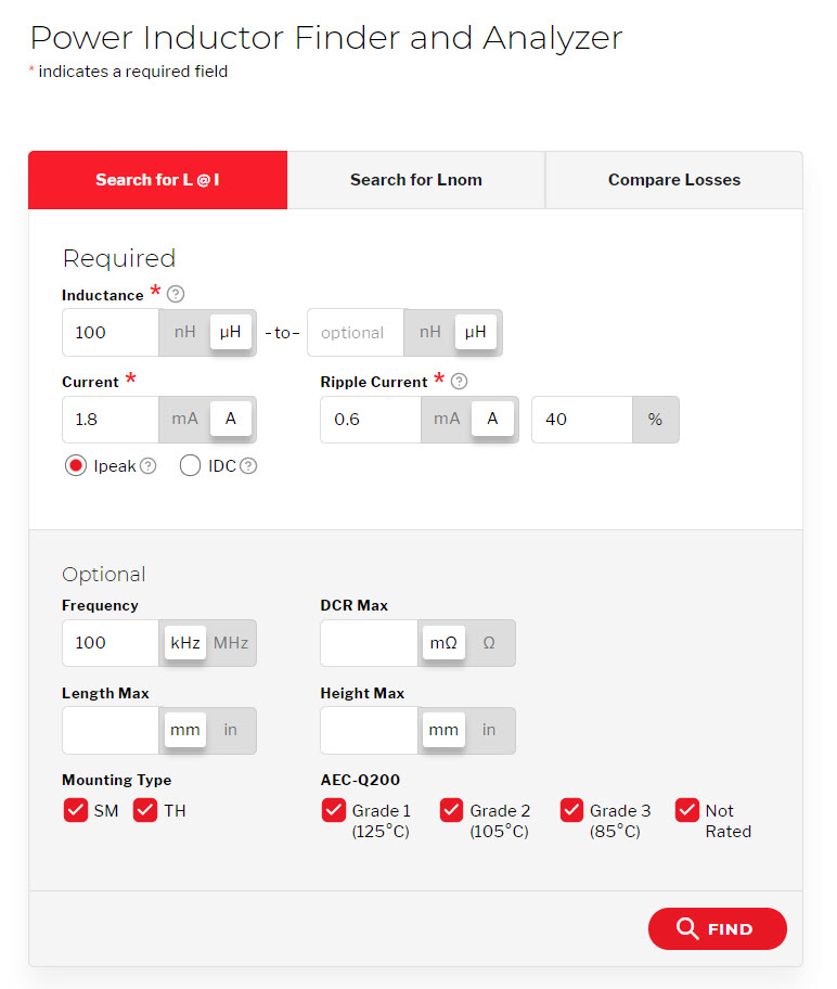
Coilcraft’s online Power Inductor Finder and Analyzer tool is designed to help circuit designers find the best performing inductor for their needs. Start by entering the basic parameters of 100 µH and 1.8 A into the tool (Figure 1). One click returns a list of suitable inductor choices.
Figure 1: Power Inductor Finder and Analyzer Tool inputs
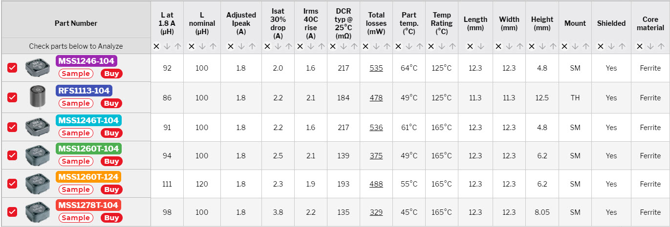
In this case, Coilcraft offers numerous inductor choices that meet the basic requirements of 100 µH and 1.8 A, and the tool provides easy ways to refine and prioritize the list according to the parameters that are most important to you. After selecting some of the most interesting components (Figure 2), more detailed performance information is provided to make a final selection.
Figure 2: Component options from Power Inductor Finder and Analyzer Tool
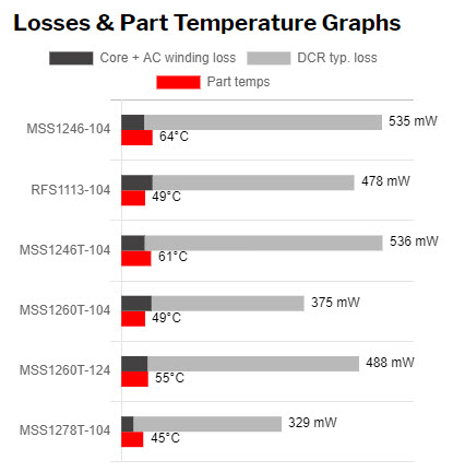
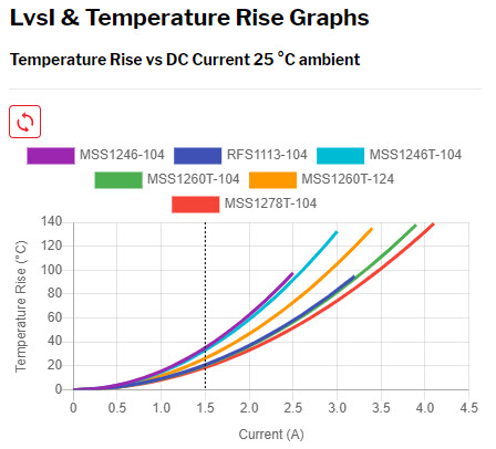
Using this information, you are now able to balance the tradeoffs between the physical size of the inductors and their various performance parameters.
Figure 3: Losses and part temperature analysis
Figure 4: L vs I and Temperature Rise
In this example, the MSS1260T-104, measuring 12 x 12 x 6 mm, provides a nice balance of performance and physical size based upon the given parameters and the fact it works well for the reference design board.
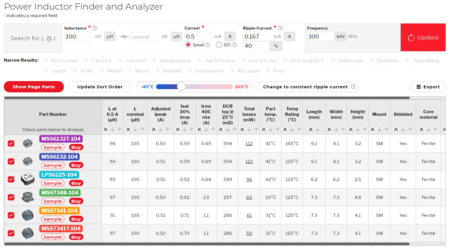
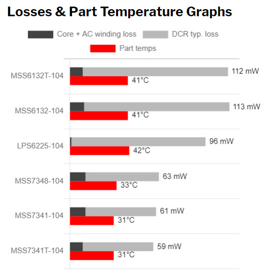
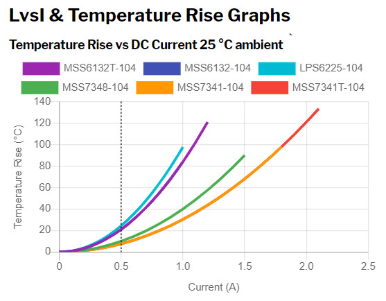
Since overall solutions size is certainly important for LiDAR systems, you will probably want to select as small an inductor as possible. In this example, the inductor is more than enough for a 0.5 A requirement. This means a much smaller inductor can be considered (Figures 5-7).
Figure 5: Comparison results of smaller components with 0.5 A (min) current ratings
Figure 6: Losses and part temperature analysis (0.5 A)
Figure 7: L vs I and Temperature Rise (0.5 A)
From this data, you see that the part with the lowest losses, the MSS7341T-104 (measuring 7.3 x 7.3 x 4.1 mm), is significantly smaller than the MSS1260T-104.
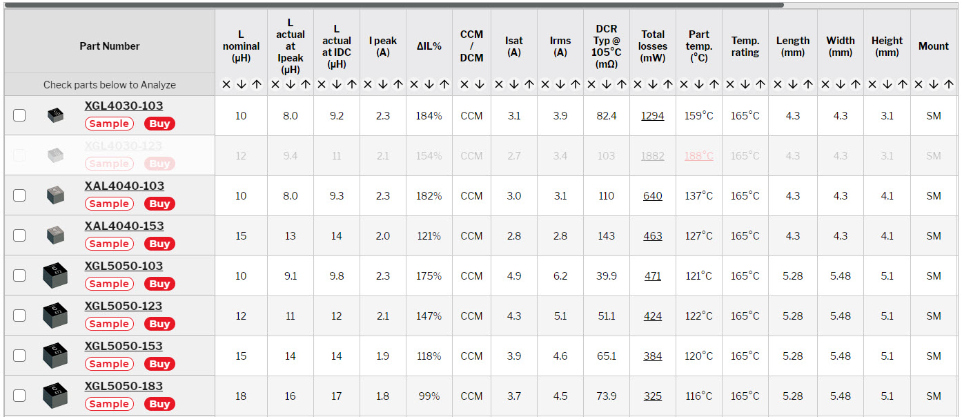
Reviewing the boost circuit more closely by using the Coilcraft DC-DC Optimizer, we can optimize the inductor selection even further.
Using the TI LM5001 switching regulator with the following assumptions yields the list of parts shown in Figure 8.
Vin: 6 to 18V
Vout: 48V
Iout: 150mA
Freq: 240kHz
Note this time we are also assuming a temperature of 105° C (ambient).
Figure 8: Coilcraft DC-DC Optimizer tool results
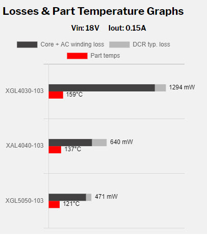
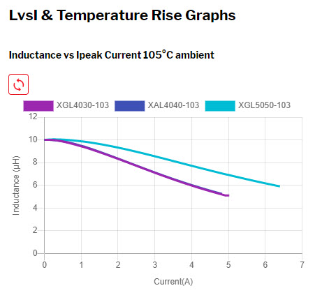
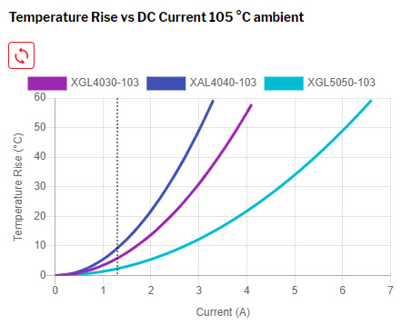
Next, let’s use the DC-DC Optimizer Tool to compare the XGL4030-103, XAL4040-103 and XGL5050-103.
Figure 9: Losses and part temperature analysis (105° C)
Figure 10: L vs I and Temperature Rise (105° C)
Figure 11: Temperature rise vs. DC current (105° C)
Based on the information in Figure 9, XGL5050-103 has the lowest losses. If the 5 mm x 5 mm size is too large for the circuit, the XAL4040-103 becomes the best choice.
As these examples demonstrate, Coilcraft has both the online tools and extensive product portfolio to help optimize your SMPS needs. For more information about the online tools or if you have any technical questions please contact us at 847-639-6400 or visit www.coilcraft.com/AEC.
AN-1956 LM5001 Boost Evaluation Board, Texas Instruments User’s Guide, SNVA393B – March 2009 – Revised April 2013