Site Settings

Warehouses
Language settings
Currency settings
Resources
Video Library
Cx Family Common Mode Chokes
0402CT Low Profile Chip Inductors
XAL7050 High-inductance Shielded Power Inductors
XGL4020 Ultra-low DCR Power Inductors

Broadband Chokes for Bias Tee Applications

How to successfully apply a DC bias onto an RF line

Introduction

The demand for increased bandwidth in data communication is continually increasing, and the integrity of RF signals has become a major design concern. In broadband bias applications, most inductors do not cover enough impedance bandwidth. By putting three or four inductors in series, bandwidth can be increased, but DC losses and filter complexity increase. Broadband chokes provide wide bandwidth in a single inductor package. This document discusses the use of broadband chokes in bias tees.

Broadband Chokes for Bias Tees

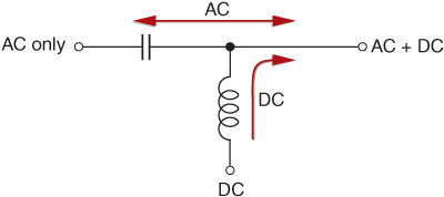
The purpose of the inductor in a bias tee, as shown in Figure 1, is to inject a DC bias while isolating the AC signal from the DC source. Ideally, any stray AC signal applied to the DC bias line will be isolated by the inductor, preventing distortion of the AC signal.

Doc1193-Fig1-schematic.gif

Figure 1. Equivalent Circuit of a Bias Tee

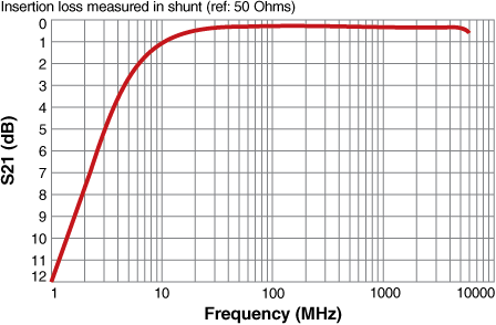
For example, a television antenna may need up to 500 mA DC injected onto the RF line, while blocking frequencies from 20 MHz to 2 GHz. Consider the isolation that can be achieved with a Coilcraft 4310LC wideband bias choke. Figure 2 shows insertion loss measurement for the coil connected in shunt from a transmission line to ground. This curve illustrates how frequencies below 10 MHz are passed through the inductor to the ground plane, and how frequencies between 10 MHz and 6 GHz are rejected by the coil and passed along the transmission line.

Doc1193-Fig2-IL_4310LC.gif

Figure 2. 4310 LC Characteristics

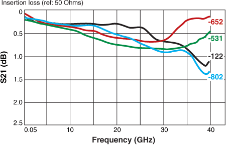
Another application requiring RF isolation is the biasing of a pin diode for use in fiber networks. Here, a 200 mAdc injection is needed on an RF line that carries frequencies from 100 MHz to 30 GHz. To meet this requirement, a Coilcraft BCR Broadband Conical Inductor can be used.

Figure 3 shows that the insertion loss from 50 MHz to 35 GHz is less than 1.0 dB when the BCR inductor is measured in shunt from a transmission line to ground.

Doc1193-Fig3-IL_BCR.gif

Figure 3. BCR Characteristics

Summary

The critical determination when choosing RF chokes for bias tees is the frequency range that needs to be blocked. Other key parameters are DC resistance, current requirements, size and cost.

A broadband bias choke is the key to successfully applying a DC bias onto an RF line. Start with identifying the frequency range of the application and then determine what the other critical parameters need to be. For assistance with your particular wideband choke selection, contact Coilcraft Technical Support.

Doc 1193

Questions or Concerns?

Ask View FAQs


General Applications

Handling and Processing

RF Inductors

Power Conversion

EMI/RFI Filtering

Special Applications