Site Settings

Warehouses
Language settings
Currency settings
Resources
Video Library
Cx Family Common Mode Chokes
0402CT Low Profile Chip Inductors
XAL7050 High-inductance Shielded Power Inductors
XGL4020 Ultra-low DCR Power Inductors

Basics of Inductor Selection (from Electronic Design magazine)

Investigating Inductor Requirements For Power and RF/Microwave Designs

Inductors are key circuit elements in many electronic designs, from power and voltage-conversion circuits to higher-frequency RF/microwave circuits. Selecting an inductor that is a good fit for a particular circuit design requires a clear understanding of inductor characteristics and how they are portrayed on product data sheets. Often referred to as coils, inductors resist changes in current by producing an electromagnetic (EM) field. Inductors are important components in many different circuits, including for chokes, filters, and impedance-matching functions. They are available in a variety of package styles and technologies (Fig. 1), and making an optimum choice of inductor for an application is a matter of understanding essential inductor performance parameters and how to compare them for different products on different data sheets.

doc1189_fig1-(1).png
Fig.1 Inductor for power and RF/microwave applications come in many shapes and sizes, along with many inductor values

Pondering Parameters

When specifying inductors for either power circuitry or RF/microwave applications, many of the same performance parameters can be considered, including inductance value, inductance tolerance, current ratings, DC resistance (DCR), self-resonant frequency (SRF), and temperature range. Some of these performance parameters may have more relevance for one type of application than another [e.g., inductor SRF and quality factor (Q) are more applicable to RF/ microwave circuits than power]. A basic understanding of each of them can simplify the search for inductors whether they are to be used in power circuits or higher-frequency RF/microwave applications.

The size of an inductor - how small it can be - is usually determined by the inductance value and acceptable losses, whether DC or AC. Both of these are critical parameters when choosing inductors, but numerous other parameters are also important when comparing and selecting inductors for different applications. Commercially available inductors come in many shapes and sizes. Knowing how to relate data-sheet specifications to performance in a specific circuit is an important step toward finding the right inductors for power and RF/microwave circuits. 

Inductance value [typically in nanoHenries (nH) or microHenries (μH)] is usually a good starting point for selecting an inductor, whether the inductance value originates from a schematic circuit diagram, from a component list for a circuit layout, as a recommended value from a computer-aided-engineering (CAE) circuit-design software program, or from some other source. Each inductor's nominal inductance value has an associated inductance tolerance (in %) which characterizes the amount of variation in the inductance value from part to part. While the required inductance value might be dictated by a circuit design, the required inductance tolerance is usually determined by the application. 

For example, in a higher-frequency RF/microwave circuit, when impedance must be closely matched by a precise inductance value, inductors with tight tolerances are usually needed, such as an inductor with inductance tolerance of ±2%. When the requirements are not as tight (e.g., in a DC-to-DC converter), an inductance value with wider tolerance, such as ±20%, can be used.

Channeling Current

A number of inductor parameters relate to current. This presents interesting challenges since an inductor's current handling ability can vary greatly by application. For example, specifying inductors for power circuits such as DC-to-DC converters can be difficult because of constantly changing current values and high peak-to-average current ratios. Selecting an inductor with a current rating based on an application's highest instantaneous current value may provide more inductor performance than needed. But basing inductor selection on the average current value may lead to an inductor with inconsistent performance during peak current periods. Because of this, careful consideration needs to be given to both peak and average current ratings when specifying inductors.

High DC current through an inductor can cause it to become saturated with magnetic flux. Under saturated conditions, the inductance value can drop sharply when magnetic materials are used as the core of the inductor. When comparing inductors, it is important to "standardize" the meaning of inductor saturation, since it can have different definitions across the industry. Many inductor suppliers define saturation current, or Isat, as the current level at which inductance drops by 10% to 20% in value, although some manufacturers have used drops of 50% in inductance to define saturation. These higher inductance drops yield higher current ratings, which can be misleading as to the usable range of current for the inductor. The drop in inductance is attributed to current saturation of the inductor core material.

Another current-related parameter, root-mean-square (RMS) current or Irms, is the current that causes the temperature of an inductor to rise a specified amount above an ambient +25°C temperature, a temperature rise associated with resistive (I2R) losses through the inductor and the resulting heating effects. It is essentially a measure of how much average current can flow through an inductor for a given temperature rise. When comparing Irms for different inductors, any comparison should also include the ambient temperature at which the current was measured.

No inductor is without some loss, and current flowing through an inductor will result in some temperature rise. Inductors are typically rated for an operating temperature range, such as a maximum ambient temperature of +85°C and some allowable temperature rise at maximum current ratings. The maximum allowable temperature for an inductor is generally the maximum ambient termperature plus the maximum temperature rise for a maximum current conditions. So, for an inductor with an ambient temperature rating of +85°C and a maximum allowable temperature rise of +40°C, the maximum operating temperature for the inductor is +85°C + 40°C = +125°C.

These temperature rises are associated with the current level through the inductor and the resulting losses. Suitable thermal management usually requires providing a proper thermal path from the inductor through the PCB. In some extreme cases, forced-air flow may be required and thermal energy may be routed to a housing or heat sink to effectively dissipate the excess heat and maintain the inductor temperature within specified limits. [More details on these phenomena are available in Document 1055-2 available from Coilcraft: "How Current and Power Relates to Losses and Temperature Rises" (www.coilcraft.com/pdfs/Doc1055_Losses_Temp_Rise.pdf)].

As with many inductor specification parameters, there is a trade-off between current ratings and temperature increases associated with resistive losses and other design parameters. Physically smaller inductors save PCB space, but suffer higher temperature rise for a given current level. For a lower rise in temperature, typically a larger inductor must be specified, occupying more PCB space in a design. An inductor's current ratings and its DC resistance (DCR) are closely related. DCR is a measure of the resistance through the inductor, such as the resistance of the wire for a wire-wound inductor, and it varies with temperature. 

Handling higher current requires an inductor with larger wire diameter or more stands of wires in the inductor to minimize losses and temperature rises. Inductor wires with larger diameters yield lower DCR values, but result in larger-sized components. The simple trade-offs is that smaller inductor size generally means higher DCR value. 

One inductor parameter that tends to carry more weight for RF/microwave applications than for power circuitry is inductor self-resonant frequency (SRF). Because the structure of any type of inductor will exhibit some capacitance, whether it is a chip, or thick-film, or wire-wound inductor type, the inductor will serve as a parallel resonant tank circuit with an SRF associated with the inductance and capacitance of the tank circuit. 

An inductor's SRF is defined by the simple equation:
SRF = f0 = 1/ [2π(LC)0.5]

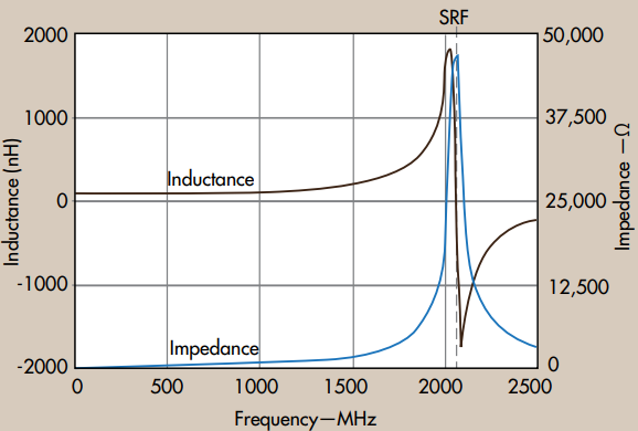
For inductors used in choke applications, the best signal blocking occurs at the SRF (Fig. 2), where impedance (and signal attenuation) is at a maximum. Below an inductor's SRF, impedance decreases with decreasing frequency.
 
doc1189_fig2.png
Fig. 2 An inductor's inductance and impedance rise sharply approching its self-resonant frequency (SRF)

For higher-order filter or impedance-matching applications, it is more important to have a relatively flat inductance curve (constant inductance as a function of frequency) close to the frequency of interest. This suggests selecting an inductor with an SRF that is well above the design frequency. A general rule of thumb is to select an inductor with an SRF that is 10 times higher than the operating frequency, although the choice of inductor value will usually determine the range of available SRF. The higher the inductance value, the lower the SRF, due to the increased winding capacitance of the inductor. 

It is important to realize that the SRF of an inductor is very much dependent upon an application and the type of PCB used in the application. The dielectrtic constant and thickness of the PCB laminate material, for example, can affect the SRF of the inductor. The circuit layout, specifically the size and position of the circuit traces and ground-plane elements, can impact the parasitic capacitance of the inductor, impacting the in-circuit SRF. Fortunately, some commercial CAE programs provide substrate-scalable inductor models, which allow PCB material characteristics and tolerances to be added to a circuit simulation, so their effects can be included in any calculations of an inductor's SRF and its effects on a circuit, such as for filtering purposes at a particular frequency. Although not always practical or possible, especially when comparing inductors from different manufacturers, it is ideal to compare SRF values that have been measured using the same test equipment, fixtures, and calibration standards. A good practice when placing an inductor where the inductance, SRF, and Quality Factor (Q factor) values are critical is to keep ground planes and other circuit elements a "coil diameter" away from the inductor. 

doc1189_fig3.png
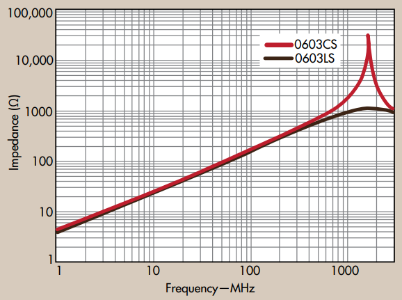
Fig. 3 Inductors exhibit changing impedance with frequency, with low-loss inductors providing high peak impedance compared to higher-loss inductors

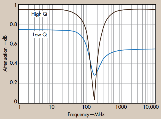
An inductor parameter with more relevance for RF/microwave applications than for power circuitry is the quality, or Q, factor (Figs. 3 and 4). It is a dimensionless parameter that essentially characterizes a circuit's bandwidth relative to its center frequency, with high Q values associated with narrow bandwidths. Q typically carries little weight when selecting inductors for power applications, as inductor losses in DC-to-DC converters are dominated by DC losses. Q is an importan parameter for inductors to be used in oscillators or narrow-bandwidth filter applications. High Q typically indicates low loss in an inductor, which can benefit circuits where power consumption must be minimized.
 
doc1189_fig4.png
Fig. 4 Inductors with high Q are well suited for narrower-bandwidth applications

The Q factor of an inductor can be calculated as a ratio of the inductor's imaginary impedance (Im[Z]) to its real impedance (Re[Z]), or 
Q = Im[Z] / Re[Z]

Inductor manufacturers typically include frequency-dependent real and imaginary losses in their measurements of Q, along with the various inductance and capacitance effects of an inductor's composite materials. 

In broadband applications where inductors are needed to block the RF signal, it may be necessary to use a number of different-valued inductors. Individual inductors with high Q values will only block a limited bandwidth, but using a few inductors in series may provide the impedance required across the desired frequency range. The tradeoff of this solution is that each element will contribute to the total losses of the circuit. 

Mechanical Properties

The inductor parameters reviewed so far describe the electrical performance of an inductor for power or RF/microwave circuits, but do not consider mechanical requirements. As mentioned earlier, inductors for these applications are available in many shapes and sizes, from compact chips and surface-mount-technology (SMT) packaged thick-film type inductors to miniature wire-wound and multilayer inductors with ferrite (magnetic) and ceramic (nonmagnetic) cores.

SMT inductors tend to be smaller than the traditional throughole package inductors they replace, although the generation of heat in smaller components at higher current levels is always a concern. 

As noted earlier, inductor DCR is typically a function of inductor size. In particular for wire-wound components, inductors constructed with larger wire diameter will be physically larger than inductors formed with smaller wire diameters, although they will also have larger current capacity, lower DCR, and increased Q. Wire-wound inductors fabricated with magnetic ferrite cores can also provide high current capacity with lower wire turns than inductors without a ferrite core. Mechanically, the traditional inductor tradeoffs have been size in exchange for a number of different electrical parameters, such as current capacity, thermal management, DCR (loss), and Q.

In general, it is important to know the test conditions under which an inductor's performance parameters were determined and, when comparing the specifications for different inductors, to compare performance parameters for the same set of test conditions (which include the test voltage, the waveshape of the test voltage, and the test voltage frequency).

Inductance value should be referenced to a test voltage, which usually has a sinusoidal wave shape. For power applications, the inductance value typiically doesn't vary much for test voltage frequencies from 20 to 500 kHz, so 100 kHz is often used as a test voltage frequency. For higher-frequency RF/microwave applications, it is necessary to compare inductance values for higher test voltage frequencies - typically in the range of an application of interest, such as 900 MHz or 1.8 GHz for wireless communications circuits. 

Understanding key inductor performance parameters can help design engineers sort through the myriad of choices for inductors when specifying components for an application. Of course, poring through piles of data sheets and catalogs can be extremely time-consuming, even with a full understanding of the key parameters. To aid designers in need of inductors for power and RF/microwave applications, Coilcraft provides several online search tools that allow users to sort through the company's lines of inductor products according to different inductor parameters. 

Coilcraft's "Power Inductor Finder" (www.coilcraft.com/finder) lets the user search for a single inductance or range of inductances and add other modifiers like ripple current, DCR, and size. Unlike a datasheet, this tool shows actual inductance at a specific current, which usually differs from a part's nominal L value. An ambient temperature slider shows how performance is affected under hotter conditions, while graphs make it easy to compare the core and winding losses and L vs. I curves of up to 6 parts. 

The "RF Inductor Finder" (www.coilcraft.com/rf-finder) offers similar capabillities and has a frequency slider to demonstrate the effects of frequency on inductance, Q, impedance, etc. Graphs allow instant comparison of Q, inductance, ESR and impedance vs frequency.

Such tools greatly help reduce the search time needed to find inductors matching a given set of requirements.
Doc 1189

Questions or Concerns?

Ask View FAQs


General Applications

Handling and Processing

RF Inductors

Power Conversion

EMI/RFI Filtering

Special Applications