Site Settings

Warehouses
Language settings
Currency settings
Resources
Video Library
Cx Family Common Mode Chokes
0402CT Low Profile Chip Inductors
XAL7050 High-inductance Shielded Power Inductors
XGL4020 Ultra-low DCR Power Inductors

Magnetics for

Texas Instruments LM5030

RoHS compliant
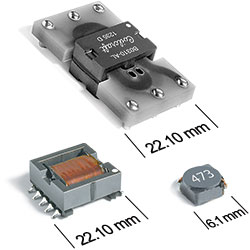
  • Specially developed for use with the Texas Instruments LM5030 100V Push-Pull Current Mode PWM Controllers
  • Low profile, high efficiency planar transformer: 33, 35 and 60 Watt versions
  • Output choke inductor with auxiliary winding
  • Magnetically shielded input choke

Buy Now:

The part number you have selected is not available through our online store.

Please click the "Request Quote" button for pricing and more information.

. in stock, ready to ship today.
Request a Sample:

Typical Application

Works with Texas Instruments LM5030

Part number Input Voltage Output Power Fsw
A9784-BL_ 36 V 75 V 3.3 V , 10 A 33 W 250 kHz
A0152-AL_ 36 V 75 V 5 V , 7 A 35 W 250 kHz
B0310-AL_ 36 V 75 V 12 V , 5 A 60 W 250 kHz

Specifications

Electrical specifications at 25°C.

Planar Transformer

Part number 1
(Hover for schematics)
Inductance
min (mH) 2
DCR max (mΩ) 3 Leakage
Inductance
max (µH)
Turns Ratio Isolation
Voltage (Vrms)
Pri Sec Pri : Sec
A9784-BL_ 1.3 0.850 0.016 3.5 1 : 0.167 1500
A0152-AL_ 1.3 0.850 0.018 2.5 1 : 0.25 1500
B0310-AL_ 1.3 0.850 0.060 2.5 1 : 0.5 1500

Input Choke Inductor

Part number 4 Inductance (µH) 5
(Tolerance: ±20%)
DCR max (Ω) 6 SRF typ (MHz) 7 Isat (A) 9 Irms (A) 10
20°C rise 40°C rise
MSS6132-103ML_   10 0.085 39.0 1.3 1.9 2.5

Output Choke Inductor

Part number 4 Power (W) Inductance
at 0A (µH) 5
(Tolerance: ±10%)
Inductance (µH) 5
(Tolerance: ±10%)
DCR max (Ω) 6 Isolation
Voltage (V) 8
Turns Ratio
main : aux
Isat (A) 9 Irms (A) 10
Main Aux
A9785-BL_   33 7.0 6.7 at 12 A 0.0066 2.0 1500 1 : 3.2 15.0 12.5
B0414-AL_   60 13.8 13.8 at 5 A 0.0098 0.68 1500 1 : 1.09 8.0 9.5
A0153-AL_   35 7.0 6.2 at 10 A 0.0066 1.3 1500 1 : 22 15.5 12.5
Notes
  1. When ordering, please specify packaging code: e.g. B0310-ALD
  2. Inductance measured between pins 1 and 3 at 250 kHz, 0.1 Vrms, 0 Adc
  3. DCR at 25°C. For other operating temperatures, use this DCR at Temperature calculator.
  4. When ordering, please specify packaging code: e.g. MSS6132-103MLC or B0414-ALD
  5. Input Choke: Inductance measured at 100 kHz, 0.1 Vrms.
    Output Choke: Inductance measured at 10.0 kHz, 0.1 Vrms.
  6. DCR at 25°C. For other operating temperatures, use this DCR at Temperature calculator.
  7. SRF measured using Agilent/HP 8753D network analyzer and Coilcraft SMD-D test fixture. Details
  8. Isolation measured from pin 5 to pins 1, 2, 3, 4.
  9. Input Choke: DC current at which the inductance drops 10% (typ) from its value without current. Details
    Output Choke: DC current at which the inductance drops 12% (typ) from its value without current. Details
  10. Input Choke: Current that causes the specified temperature rise from 25˚C ambient. Details
    Output Choke: Current that causes a 40˚C temperature rise above 25˚C ambient. Details

Termination:

  • RoHS-compliant. 260°C compatible.
    Planar transformers: Matte tin over nickel over brass terminations
    MSS6132: Gold over nickel over phos bronze terminations
    Output choke inductors - Tin-silver over tin over nickel over phos bronze terminations

Packaging:

  • D = 13″ machine ready reel. EIA-481 embossed plastic tape (250 parts per full reel). Quantities less than full reel available: in tape (not machine ready) or with leader and trailer ($25 charge).
  • B = Less than full reel. In an effort to simplify our part numbering system, Coilcraft is eliminating the need for multiple packaging codes. When ordering, simply change the last letter of your part number from B to D.
Environmental
Environmental:
RoHS compliant
Ambient temperature range:
−40°C to +85°C
Storage temperature range:
Component: −40°C to +85°C
Tape and reel packaging: −40°C to +80°C
Failures in Time (FIT) / Mean Time Between Failures (MTBF):

Performance curves

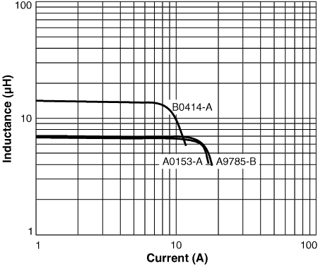
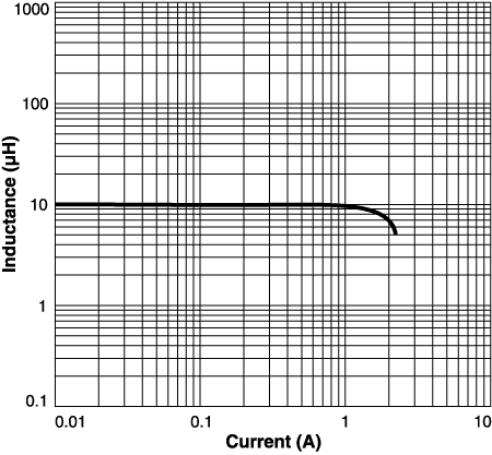
Inductance vs Current

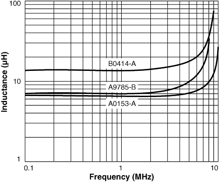
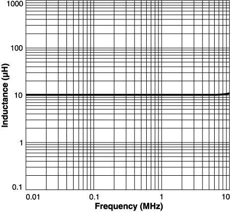
Inductance vs Frequency

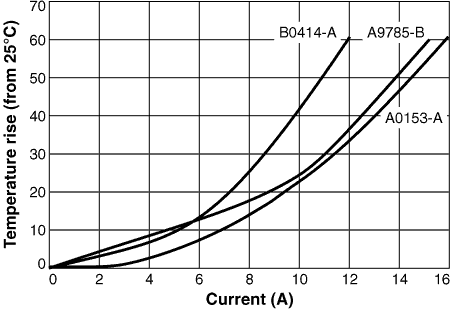
Temperature Rise vs Current

Inductance vs Current

Inductance vs Frequency

Schematics

Planar Transformer                                         Output Choke Inductor
lm5030schematic-(1).gif


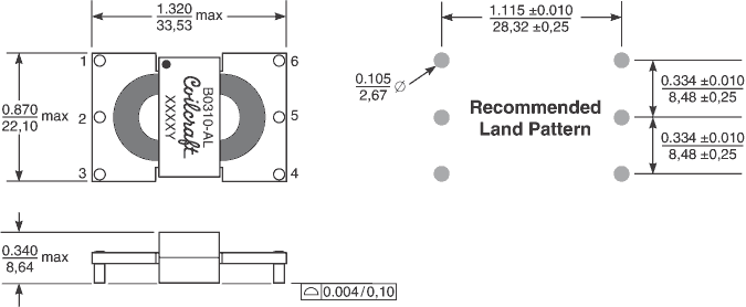
Physical characteristics

lm5030d1.gif
dims_inches_mm-(2).gif

Tape and Reel specification

tapereel_pl.gif
Parts per reel Reel dimensions (mm) Tape dimensions (mm) Orientation
  13" (330 mm) A B C D E W P Po P1 H T lm5030tape-reel.gif
A9784, A0152, B0310 250 330 100 13 62,4 56,4 56 28 4 2 8,86 0,36

General specification

Weight:
9.5 – 10.9 g
Packaging:
250/13″ reel 56 mm tape

Soldering

Resistance to soldering heat:
Three reflows at >217°C for 90 seconds (+260°C ±5°C for 20 – 40 seconds), allowing parts to cool to room temperature between.
Refer to Soldering Coilcraft Components before soldering.

Related product series