Site Settings

Warehouses
Language settings
Currency settings
Resources
Video Library
Cx Family Common Mode Chokes
0402CT Low Profile Chip Inductors
XAL7050 High-inductance Shielded Power Inductors
XGL4020 Ultra-low DCR Power Inductors

Tunable Low Profile

RF Inductors 148 Series

RoHS compliant
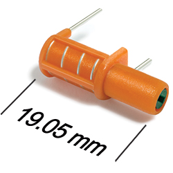
  • 0.300″ / 7,6 height is ideal for low profile applications
  • Windings are precision molded into plastic for mechanical and electrical stability
  • Threaded Carbonyl J core with a slotted socket
  • Extremely economical, even in small quantities
  • RoHS-compliant. Tin-silver over copper terminations.
  • Samples of all values are available in Coilcraft Designer's Kit M304
  • Tune with our handy 3-in-1 "TriTuner" tuning tool

Buy Now:
Count Unit price
1 $3.19
100 $2.62
250 $1.84
500 $1.36
1000 $0.96
2500 $0.57
5000 $0.43

For high volume or non-stock items, request a quote.

. in stock, ready to ship today.
Request a Sample:

Designer's Kit:
Kit Values Price
M304 33 (3 of each) $60.00

Specifications

Electrical specifications at 25°C.

Part number 1 Color Turns Inductance (nH) 2 Test frequency
(MHz)
Q min
at L nom 3
SRF min (MHz)
No core
nom
min 4 nom max
148-01J12L Brown 35 38 39 40 50.0 88 3200
148-02J12L Red 44 46 52 58 50.0 96 1560
148-03J12L Orange 56 60 73 86 50.0 106 1200
148-04J12L Yellow 74 77 101 125 50.0 112 980
148-05J12L Green 92 96 130 164 50.0 112 820
148-06J12L Blue 114 120 170 220 50.0 112 720
148-07J12L Violet 142 154 222 290 50.0 110 620
148-08J12L Gray 168 176 262 346 25.0 106 570
148-09J12L White 198 208 310 410 25.0 104 490
148-10J12L Black 10½ 237 250 375 500 25.0 90 450
148-11J12L Brown 11½ 276 290 435 580 25.0 84 410
148-12J12L Red 12½ 315 338 500 666 25.0 66 350
148-13J12L Orange 13½ 344 362 540 710 25.0 64 320
Notes
  1. To order fixed inductance parts without cores, eliminate the “J12”, e.g. 148-13L.
  2. Inductance readings taken at test frequency on an Agilent/HP 4342A Q meter with 1/2″ long, 16 AWG tinned copper wire soldered along the leads and bent at 90°, 1/4″ from standoffs. Inductance values at 50 MHz calculated from Cp readings. Inductance values at 25 MHz read at standard Q meter frequency (blue line)
  3. Q readings taken at test frequency on an Agilent/HP 4342A Q meter with 1/2″ long, 16 AWG tinned copper wire soldered along the leads and bent at 90°, 1/4″ from standoffs.
  4. L min measured with core halfway out top of form. L max measured with core centered in the windings.

Termination:

  • Tin-silver over copper
Environmental
Environmental:
RoHS compliant
Ambient temperature range:
−40°C to +85°C
Storage temperature range:
Component: −40°C to +85°C
Packaging tubes: −40°C to +80°C
Failures in Time (FIT) / Mean Time Between Failures (MTBF):

Physical characteristics

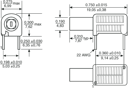
148d.gif
dims_inches_mm.gif

General specification

Core Material:
Carbonyl J. Core length: 0.375 in / 9,5 mm
Weight:
0.7 – 1.2 g
Packaging:
30 per tube

Soldering/Washing

Resistance to soldering heat:
Wave solder only. Recommended maximum board surface temperature of 168°C (334°F) for no more than three seconds. Pre-heating is recommended to minimize time over the solder nozzle.
Refer to Soldering Coilcraft Components before soldering.
PCB Washing:
Tested to MIL-STD-202 Method 215 plus an additional aqueous wash. More info.