Note: This example uses RVAR1 ( = k1 * sqrt(Frequency)). In your circuit, substitute the numerical value of k1 given in the model table for the specific model value you are using, into the XFORM statement.
Z(S) = RVAR1 = k1*sqrt(Frequency), where Frequency is in degrees
Since S is the frequency in radians, Frequency must be converted to degrees.
The resulting frequency-dependent resistance will be in Ohms units.
1/Z(S) = XFORM = 1/k1/(−S*S/4/3.14159^2)^0.25
Note: In your circuit, substitute the numerical values of k3, k4, and k5 given in the model table for the specific model value you are using, into the XFORM statement.
Z = S*LVAR = k3-(k4*LOG(k5*Frequency)), where Frequency is in degrees
The "LOG" function used here is the natural logarithm (base e, not base 10).
Since S is the frequency in radians, Frequency must be converted to degrees.
Since the inductance is given in uH units, the LVAR expression is converted as shown below.
1/Z = XFORM = 1/(S*1e-6*( k3-(k4*LOG(k5*(S/(2*3.14159265))))))
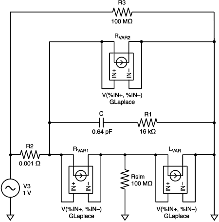
Place and wire the other parts of the model in the schematic. If the specific model inductance element is a fixed value inductor, use the IND part instead of the GLaplace part. Edit the part values to match those of the model table values for the specific inductor you are simulating. See the example schematic and netlist shown below.
In the case where two GLaplace elements are in series, a large-valued resistance to ground (Rsim) was added to prevent a floating node error. The large-valued resistance (R3) was added to measure voltage across the entire model.
Note: Make sure to substitute the specific model table values for each element (part) of the inductor model into the schematic.
* Example Schematics Netlist *
R_R2 $N_0002 $N_0001 0.001 V_V3 $N_0002 0 DC 0V AC 1v R_R3 $N_0002 0 10meg R_Rsim 0 $N_0003 10meg G_Rvar2 $N_0001 0 LAPLACE { V($N_0001, 0) } { + 1/k2/(-S*S/4/3.14159^2)^0.25} R_R1 $N_0004 0 16000 G_Lvar $N_0003 0 LAPLACE { V($N_0003, 0) } { + 1/(S*1e-6*(k3-(k4*LOG(k5*(S/(2*3.14159265)))))) } G_Rvar1 $N_0001 $N_0003 LAPLACE { V($N_0001, $N_0003) } { + 1/k1/(-S*S/4/3.14159^2)^0.25} C_C $N_0001 $N_0004 .64pF
Include the following Macros in your Probe trace analysis to see frequency vs. inductance, impedance, phase angle (in degrees), and Q factor:
PI = 3.14159265 L=(IMG(V(R3:1)/I(R2))/(2*pi*FREQUENCY) Z = V(R3:1)/I(R2) ANG = (180/PI)*ARCTAN((IMG(V(R3:1)/I(R2)))/(R(V(R3:1)/I(R2)))) QFACT = ABS((IMG(V(R3:1)/I(R2)))/(R(V(R3:1)/I(R2))))