Site Settings

Warehouses
Language settings
Currency settings
Resources
Video Library
Cx Family Common Mode Chokes
0402CT Low Profile Chip Inductors
XAL7050 High-inductance Shielded Power Inductors
XGL4020 Ultra-low DCR Power Inductors

Model library for LTspice®

LTspice is a high performance SPICE simulator that simplifies the design of switching regulators. The software is provided free by Analog Devices.  LTspice includes a library of models for a limited number of Coilcraft inductors. These models are included in the standard inductor library file and are updated periodically.

Coilcraft has created a set of advanced frequency dependent and time domain (impedance) models for modelling the small signal response of inductors. These models are based on the same schematic, element values, and coefficients for variable elements which are provided in our SPICE model documents for each inductor series. We have also developed saturation models for our soft-saturating inductors.

Download Coilcraft Advanced model libraries 

To include the advanced library copy the lib folder from the CoilcraftLTAdvLib.zip file to C:\Users\Documents\LTspiceXVII The folder may have a different name or path depending on the version installed. See below for more detailed instructions.

CoilcraftLTAdvLib.zip Includes all Coilcraft power and RF inductors for small signal AC analysis.

Installing Coilcraft Advanced model libraries 

  1. Download the CoilcraftLTAdvLib.zip file
  2. Extract the .zip file and navigate into the extracted folder
    Picture8.png
  3. Copy the lib folder from the extracted folder
  4. Navigate to “C:\Users\(YourUserNameHere)\Documents\LTspiceXVII”
    • This should be the default location for LTSpice library files
    • It would be advisable to create a backup copy of the original lib folder located here before adding the new library if you would like to be able to revert back later on.
    Picture9.png
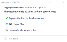
  5. Paste the new lib folder from the CoilcraftLTAdvLib.zip here and your LTSpice sub circuit and symbols folders should now be populated with the Coilcraft Advanced Inductor LTSpice library. 
    • If you already have the Coilcraft Advanced model library and are updating you will need to choose to replace the destination files.
    • You will need to close and restart LTSpice for the new files to appear
    Picture10.png

Using Coilcraft Advanced models

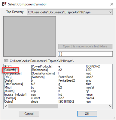
  1. To use a Coilcraft Advanced inductor model simply select the place component icon
    Picture11-(1).png
  2. Double click on the new Coilcraft folder
    Picture12-(1).png
  3. Select the series of the part you would like to use and double click it
  4. Place the inductor in your circuit and right click on the inductor to open the Component Attribute Editor
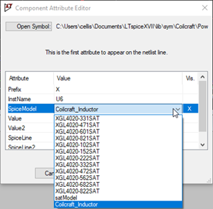
  5. In the Component Attribute Editor window triple click on the SpiceModel value which will show a default value of “Coilcraft_Inductor”
    Picture13.png
  6. Once the dropdown menu appears select your inductor value
  7. Setup of the inductor other than integrating into the particular test circuit is now complete

Using Coilcraft saturation models

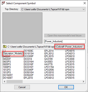
  1. To use a Coilcraft Inductor saturation model simply select the place component icon and navigate to the Coilcraft Saturation Models folder which can be found in \Coilcraft\Power_Inductors
    Picture14.png
  2. Once a series has been selected place the part into your circuit
  3. To select a value from the series right click on the inductor to open the Component Attribute Editor window
  4. Triple click on the SpiceModel value which is “Coilcraft_Inductor” by default to get the dropdown menu of available values
    Picture15.png
  5. Once the value is selected and the inductor is placed in your circuit the simulation is ready to go

Plotting Waveforms 

To plot Inductance vs frequency (best viewed in Cartesian form):
Im(V(n001)/Ix(U1:1))/(2*pi*frequency)
To plot Impedance vs frequency (best viewed in Bode Logarithmic form):
V(n001)/Ix(U1:1)
To plot ESR vs frequency (best viewed Bode Logarithmic form):
Re(V(n001)/Ix(U1:1))
To plot Q factor vs frequency (best viewed in Cartesian form):
ABS(Im(V(n001)/Ix(U1:1))/Re(V(n001)/Ix(U1:1)))
*note voltage node names may be different.  It is up to user to ensure voltage nodes are across the inductor.