Website-Einstellungen

Lager
Spracheinstellungen
Währungseinstellungen
Produkte
Informationsmaterial
Video-Bibliothek
Cx Family Common Mode Chokes
0402CT Low Profile Chip Inductors
XAL7050 High-inductance Shielded Power Inductors
XGL4020 Ultra-low DCR Power Inductors

A Guide to Forward-mode Transformers

Forward-mode Transformers

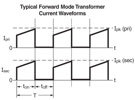
FM_waveform.png
Typical Forward-Mode Transformer Current Waveforms

Forward-mode transformers, also known as forward-converter transformers, transformers for forward- mode topology, or simply forwards, are used to provide circuit isolation and voltage transformation in forward-mode DC-DC converters. Forward mode includes simple forward converters as well as half-bridge, full-bridge, and active-clamp types.

Forward-mode converters are used for output current requirements up to approximately 15 Amps, or when high efficiency is required. The forward-mode topology is preferred for high output power levels up to about 300 Watts, although you can use two-switch forward-mode topologies power levels down to a few watts. Forward-mode transformers are attractive because they allow you to achieve efficiencies up to 95 – 97%. This article discusses forward-mode transformers and applications for which Coilcraft forward-mode transformers are best suited.

What is a forward-mode transformer?

The core is not used for energy storage in forward-mode transformers. Instead, the primary and secondary conduct simultaneously (and directly) when the switch is on, and energy is processed directly through the transformer. This is different from flyback topology, in which energy is stored in the magnetic field of the transformer during the first half of the conduction cycle and then released to the secondary winding(s) connected to the load in the second half of the cycle. Flyback transformers require a specific magnetizing inductance and have a gapped-core construction, which allows high energy storage without saturating the core. Ideally, the forward-mode transformer has high (primary) magnetizing inductance, which serves to minimize the magnetizing current.

How does a forward-mode controller work?

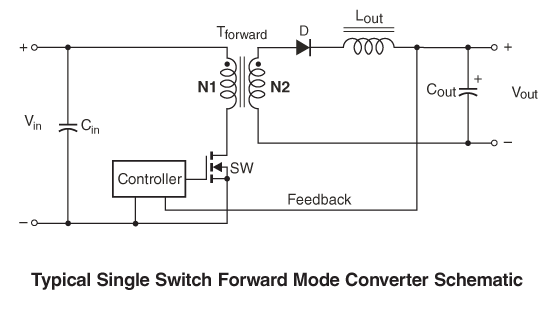
SSF_schematic.png
Typical Single Switch Forward Mode Converter Schematic

Forward converters are basically buck converters that use a forward-mode transformer for isolation.

The forward-mode controller opens and closes the switch with the appropriate duty cycle to achieve the required output voltage. The switch (SW) is commonly a MOSFET, but is occasionally a bipolar transistor and sometimes GaN or SiC. Various combinations of turns ratios and duty cycles can be used to achieve the required output voltage according to this equation:

Vout = Vin × Nsec / Npri × D

Vout = output voltage
Vin = input voltage
Nsec / Npri = N2 / N1 = transformer secondary to primary turns ratio
D = duty cycle = ton / (ton + toff)

The basic single-switch forward cycle includes the following portions:

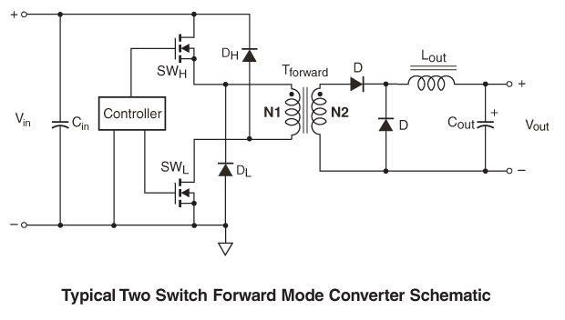
TSF_schematic.png
Typical Two Switch Forward Mode Converter Schematic

The lower rms secondary current in the forward-mode design compared to a similar flyback design can mean lower losses in the secondary winding, even if the flyback design has a higher number of turns. This lower secondary loss is one reason forward-modes typically provide higher efficiency than similar flyback designs. Another reason is the flyback output capacitor must also handle higher current than the forward-mode design, adding capacitor losses to the equation.

A two-switch forward-mode converter (also called an asymmetrical half-bridge forward converter) has two FET switches which are sometimes integrated into a single controller IC. One advantage of a two-switch forward converter is the voltage across the switches is clamped to the input voltage, allowing a wider input voltage range. The maximum operating voltage of a two-switch forward converter approaches the FET voltage rating, whereas the maximum operating voltage of a single-switch forward converter is only half of the FET voltage rating.

Another advantage is the two-switch topology does not require an auxiliary reset winding, thus it can utilize a simpler (and lower-cost) forward-mode transformer design.

What are typical forward-mode transformer applications?

Forward-mode transformers are appropriate for many applications, including:

Off-the-shelf forward-mode transformers are available for many applications where low cost, small size, and high efficiency are required. They are typically used in DC-DC controllers in the telecommunications (telecom) voltage range of 36 – 72 Vdc, sometimes at extended voltages ranging from 9 – 36 Vdc.

Forward-mode transformers are commonly used for output current up to about 15 Amps and output power up to approximately 300 Watts. Coilcraft offers standard, off-the-shelf forward-mode wirewound transformers with power capabilities ranging from a few Watts to up to 60 Watts. When higher current and power is required, Coilcraft also offers standard planar transformers for forward-mode, push-pull, or half-bridge / full-bridge topologies in power ratings from 30 Watts to 800 Watts.

How do I select the Coilcraft forward-mode transformer that best fits my application requirements?

As with any electronic component, selecting forward-mode transformers requires you to evaluate and balance a variety of competing trade-offs in component performance, size, efficiency, cost, and weight.

High energy storage, high-power/high-current applications generally require large transformers to avoid core saturation. High output current requires large wire size to avoid overheating the wire insulation. Large cores require large bobbins with a longer mean winding length, resulting in higher DCR. High switching frequencies can reduce component size due to a lower inductance requirement, but core losses increase as frequency increases, leading to lower efficiency. Core and winding losses typically increase as size decreases, therefore, attempts to use a transformer that is too small for a given application may lead to overheating. Coilcraft off-the shelf forward transformers are designed to optimize these competing requirements, resulting in a compact, efficient, and cost-effective transformer.

Coilcraft offers a helpful selection guide for finding the right off-the-shelf flyback transformer based on:

  1. The required transformer input voltage range (Vmin is worst case)
  2. The required output voltage(s)
  3. The required output rms current or power. Approximate output power: Pout = Vout × Iout.

Coilcraft displays its wirewound forward-mode transformers in ascending order by output power. Find the appropriate power rating, and then search for your input voltage range and output voltage. If your power requirement is higher than 60 Watts, or if a planar-style transformer is desired, select from our many off-the-shelf planar transformers.

Don't Forget the Output Inductor - Lout

All forward converters need an output inductor (Lout) as shown in the schematics above. Coilcraft offers inductor selection guides and tools, such as the Power Inductor Finder tool to help you find the inductor you need based on inductance value and current rating. Try our Power Inductor Finder now.

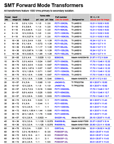
SN_Forward_Mode.gif
Forward-mode transformers are shown in ascending order by output power. First, find the appropriate power rating, then the input voltage range and finally, the output voltage.

References

Mammano, Robert A., 2017. Fundamentals of Power Supply Design. Texas Instruments.

Dixon, Lloyd H., 2001. Magnetics Design for Switching Power Supplies. Unitrode Magnetics Design Handbook.

Colonel Wm. T. McLyman, 1988. Transformer and Inductor design Handbook. 2nd ed., Marcel Dekker.

Tools

Power Inductor Finder

Related Application Notes

Structured Design of Switching Power Transformers, Coilcraft Document 627

What's Next

View more: Getting Started Series