Website-Einstellungen

Lager
Spracheinstellungen
Währungseinstellungen
Produkte
Informationsmaterial
Video-Bibliothek
Cx Family Common Mode Chokes
0402CT Low Profile Chip Inductors
XAL7050 High-inductance Shielded Power Inductors
XGL4020 Ultra-low DCR Power Inductors

A Guide to Flyback Transformers

What are Flyback Transformers?

A flyback transformer is a coupled inductor with a gapped core. During each cycle, when the input voltage is applied to the primary winding, energy is stored in the gap of the core. It is then transferred to the secondary winding to provide energy to the load. Flyback transformers are used to provide voltage transformation and circuit isolation in flyback converters.

Flyback transformers are the most popular choice for cost-effective, high-efficiency isolated power supply designs up to approximately 120 Watts. They provide circuit isolation, the potential for multiple outputs and the possibility of positive or negative output voltages. They can also be regulated over a wide range of input voltage and load conditions. Because energy is stored in the transformer, the flyback topology does not require a separate output filter inductor like the other isolated topologies. This reduces the component count and simplifies the circuit requirements. This article discusses flyback transformers and applications for which they are best suited.

What is a flyback?

In the flyback topology, energy is stored in the magnetic field of the transformer during the first half of the switching cycle and then released to the secondary winding(s) connected to the load in the second half of the cycle. Flyback transformers feature a gapped-core construction, which allows high energy storage without saturating the core. This energy storage aspect distinguishes flybacks from other topologies such as forward-mode where energy transfers immediately from primary to secondary. Flyback transformers are also known as coupled inductors, because they have a gapped core construction and store energy in the core.

How does a flyback controller work?

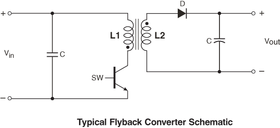
Flyback_Schematic.png
Figure 1

The flyback topology is based on a buck-boost topology, with the transformer providing isolation and, if needed, voltage transformation by turns ratio. The schematic shown in Figure 1 represents a typical flyback circuit.

The most commonly used switch (SW) in a flyback converter is a MOSFET (Metal Oxide Semiconductor Field Effect Transistor), but occasionally a bipolar transistor and sometimes GaN (gallium nitride) or SiC (silicon carbide) are used. The flyback controller opens and closes the switch with the appropriate duty cycle to achieve the required output voltage. The duty cycle of flyback transformers typically does not exceed 0.5. Various combinations of turns ratios and duty cycles can be used to achieve the required output voltage according to this equation:

Vout = Vin*(Ns/Np)*(D/(1-D)) where:
Vout is the output voltage
Vin is the input voltage
Ns = secondary turns
Np = primary turns
D = duty cycle = ton/(ton + toff)

The basic flyback cycle includes the following portions:

  1. When the FET (Field Effect Transistor) SW is closed (ON), current is conducted through the transformer primary. This sets up a magnetic field in which energy is stored in the core. The combination of winding polarity (identified by the polarity dots) reverse biases the output diode to ensure that no energy is transferred to the secondary (load) when the switch is closed. During this portion of the cycle, current in the primary is ramping up over time to store energy (= ½LI2).
  2. When the FET is opened (OFF) the magnetic field collapses, transferring the stored energy to the secondary winding and, ultimately the load. At the close of the switch, current in the secondary is at its peak and ramps downward as the stored energy is transferred to the load.
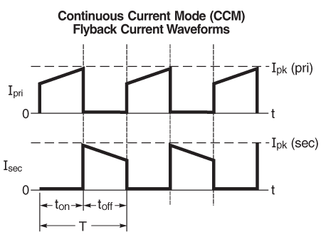
CCM_waveform.png
Figure 2
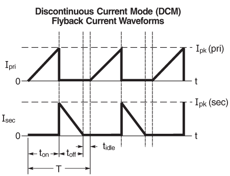
DCM_waveform.png
Figure 3

If the FET is turned back on before all of the flyback energy is transferred to the secondary, the secondary current never reaches zero. This is referred to as continuous conduction mode (CCM). An example of a CCM waveform is shown in the Figure 2. If the stored flyback energy is completely emptied to the secondary before the FET is turned back on, the secondary current reaches zero before the end of the period, creating an "idle time" (tidle) during the cycle. This is called discontinuous conduction mode (DCM). An example of a DCM waveform is shown in the Figure 3. Transformers may be designed for CCM, DCM, or both. Flyback transformers may operate in both CCM and DCM modes, depending on the input voltage and load conditions.

When designing a flyback transformer, the worst-case condition of maximum load at the minimum input voltage creates the highest (peak) primary current requirement. Select a transformer that has a peak primary current (Ipk) or primary saturation current (Isat) that is well above the expected primary current peak for your application. If the application's peak primary current draw exceeds the transformer rating, core saturation will cause the primary inductance to drop. If the load requires more energy at this point, the energy storage capability of the transformer will be exceeded and the load will not receive the required energy. This will lead to loss of regulation, therefore the peak primary current (Ipk) or primary saturation current (Isat) of a flyback transformer is a critical parameter.

What are typical flyback transformer applications?

You can use Flyback transformers in many applications, including:

Off-the shelf flyback transformers are available for many applications where low cost, small size, and high-efficiency are required. They are typically used in DC-DC controllers in the telecommunications (telecom) voltage range of 37 – 72Vdc, sometimes at extended voltages ranging from 2 – 400 Vdc, and also within the universal AC line input voltage range (85 – 265 Vac ).

Flyback transformers are commonly used for output current below about 10 Amps and output power below about 100 Watts. Coilcraft offers standard, off-the-shelf flyback transformers with power capabilities ranging from a few Watts to up to around 120 Watts. When higher current and power is required, forward-mode, push-pull, or half-bridge / full-bridge topologies become more efficient alternatives.

How do I select the Coilcraft flyback transformer that best fits my application requirements?

As with any electronic component, selecting flyback transformers involves a multitude of competing trade-offs in performance, size, efficiency, cost, and weight. Careful selection of core size is required to achieve high energy storage without core saturation. Wire size (diameter) must be chosen carefully to provide high output current without overheating the wire insulation. Core shape and bobbin selection must be optimized to minimize the winding length and achieve the lowest possible DCR. High switching frequency can be used to reduce transformer size, but care must be taken to avoid increased AC losses from core loss, proximity effect, and skin effect.

Coilcraft offers a helpful selection guide for finding the right off-the-shelf flyback transformer based on:

Coilcraft displays its flyback transformers by input voltage range, and sorts within that category by output power.

References

Mammano, Robert A., 2017. Fundamentals of Power Supply Design. Texas Instruments.
Colonel Wm. T. McLyman, 1988. Transformer and Inductor design Handbook. 2nd ed., Marcel Dekker.

What's Next?

View more: Getting Started Series