Site Settings

Warehouses
Language settings
Currency settings
Resources
Video Library
Cx Family Common Mode Chokes
0402CT Low Profile Chip Inductors
XAL7050 High-inductance Shielded Power Inductors
XGL4020 Ultra-low DCR Power Inductors

Soldering Coilcraft Components

Concerns regarding the use of water-soluble flux

Water soluble fluxes can leave weak organic acid (WOA) residues that must be thoroughly removed from all pc board components. All fine wire components, like many inductors, should be considered potentially susceptible.

Thorough rinsing and drying is required to remove water-soluble flux residue from all pc board areas, especially irregular component surfaces where contaminants can easily collect. If not removed completely, water-soluble flux residue can cause immediate or latent corrosion.

Coilcraft strongly recommends consulting both the solder and water-soluble flux manufacturer for complete application information.

For further reference:

Soldering surface mount components

Download Application Note – Soldering surface mount components

For all soldering methods, the optimal reflow profile for a circuit board assembly is dependent on several factors other than just the Coilcraft component and the chosen solder paste, such as the size and layout of all components. Large parts may require higher temperatures or a longer preheat time, whereas smaller parts (0201, 0402) may require extra considerations to avoid damage to the components.

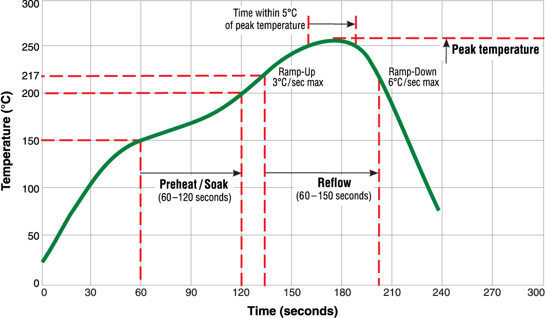
Following are general guidelines (See Table 1.) that should only be considered a starting point for development of a proper reflow profile that considers, at a minimum, part size, the specific customer-chosen solder alloy, and the PCB component population. No single reflow profile covers all possible circuit board designs. 

Table 1. General Guidelines
  RoHS Units
Preheat / Soak Temperature 150 – 200 °C
Preheat / Soak Duration 60 – 120 seconds
Ramp-up Rate 3 °C / second
Typ. Reflow Temperature 217 °C
Peak Temperature 255 – 260 °C
Time Within 5 °C of Peak 30 seconds
Time Above Reflow Temperature 60 – 150 seconds
Ramp-down Rate 6 °C / second
 

Doc755-Typical_RoHS-Reflow-Profile.gif

This typical reflow profile is provided only as a guide.

Soldering through-hole components

All our RoHS-compliant parts are backward compatible with tin-lead soldering processes.

For all soldering methods, the optimal soldering profile for a circuit board assembly is dependent on the solder material, solder amount, flux, temperature limit of each soldered component, heat transfer characteristics of the circuit board and component materials, and the layout of all components. The temperature vs. time limitation of the least robust component of the circuit board assembly ultimately dictates the optimal temperature profile. For this reason, Coilcraft does not provide soldering profiles for our components.

CAUTION: All of Coilcraft's through-hole components are designed to be wave soldered and it is not recommended to use a reflow soldering procedure. The higher temperatures of reflow soldering may damage these components.

Coilcraft's through-hole components can be successfully wave soldered as long as care is taken throughout the process. For many of the components, it is essential to minimize the circuit board temperature and the time spent over the solder nozzle. In order to achieve a quality bond without damaging the components, Coilcraft recommends preheating the board for up to three minutes and limiting the time the board spends over the solder nozzle to three seconds.

For further reference: